40 Pin GPIO 接口
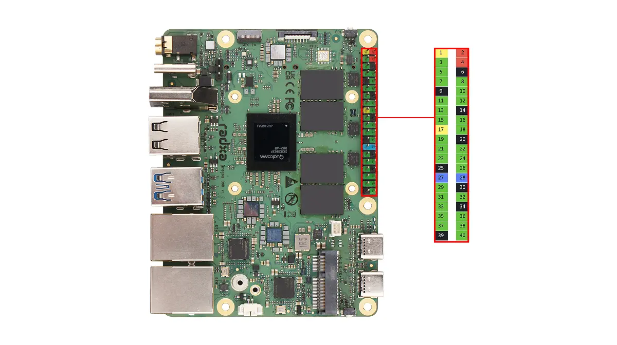
瑞莎 Dragon Q8B 板载 40-Pin GPIO(通用输入输出)接口,为硬件扩展提供了高度灵活的接口支持。
用户可以通过 40-Pin GPIO 接口连接各类传感器、执行器、通信模块、显示屏以及其他嵌入式外设,从而快速实现物联网(IoT)、机器人控制、工业自动化等领域的原型开发与功能验证。
危险
使用 40-Pin GPIO 接口时,请注意引脚和外设的接线,请确保引脚连接正确,不当操作可能导致设备硬件损坏。
GPIO 功能
Dragon Q8B 支持通过板载 GPIO 引脚连接外部设备,并支持 UART、SPI、I2C 等多种复用功能。
| Function4 | Function3 | Function2 | Function1 | Function0 | Pin# | Pin# | Function0 | Function1 | Function2 | Function3 |
|---|---|---|---|---|---|---|---|---|---|---|
| 3V3 | 1 | 2 | 5V | |||||||
| SPI9_MISO | UART9_CTS | I2C9_SDA | GPIO_41 | 3 | 4 | 5V | ||||
| SPI9_MOSI | UART9_RFR | I2C9_SCL | GPIO_42 | 5 | 6 | GND | ||||
| SPI4_CS_3 | GPIO_175 | 7 | 8 | GPIO_63 | UART17_TX | |||||
| GND | 9 | 10 | GPIO_64 | UART17_RX | ||||||
| SPI4_CS_1 | I2C5_SDA | GPIO_111 | 11 | 12 | GPIO_174 | UART4_RX | SPI4_CS_0 | |||
| HS-UART18_CTS | SPI18_MISO | UART18_CTS | I2C18_SDA | GPIO_66 | 13 | 14 | GND | |||
| HS-UART18_RFR | SPI18_MOSI | UART18_RFR | I2C18_SCL | GPIO_67 | 15 | 16 | GPIO_68 | UART18_TX | SPI18_SCKL | HS-UART18_TX |
| 3.3V | 17 | 18 | GPIO_110 | |||||||
| SPI20_MOSI | UART20_RFR | I2C20_SCL | GPIO_88 | 19 | 20 | GND | ||||
| SPI20_MISO | UART20_CTS | I2C20_SDA | GPIO_87 | 21 | 22 | GPIO_92 | SPI20_CS_2 | |||
| SPI20_SCKL | UART20_TX | GPIO_89 | 23 | 24 | GPIO_90 | UART20_RX | SPI20_CS_0 | |||
| GND | 25 | 26 | GPIO_91 | SPI20_CS_1 | ||||||
| SPI9_SCKL | UART9_TX | I2C8_SDA | GPIO_43 | 27 | 28 | GPIO_44 | I2C8_SCL | UART9_RX | SPI9_CS_0 | |
| SPI6_CS_0 | UART6_RX | GPIO_157 | 29 | 30 | GND | |||||
| SPI6_SCKL | UART6_TX | GPIO_156 | 31 | 32 | GPIO_114 | CCI_I2C_SCL0 | GCC_GP2_CLK_MIRA | |||
| GCC_GP3_CLK_MRIA | CCI_I2C_SDA1 | GPIO_115 | 33 | 34 | GND | |||||
| SPI4_MISO | UART4_CTS | I2C4_SDA | GPIO_171 | 35 | 36 | GPIO_112 | I2C5_SCL | SPI4_CS_2 | ||
| HS-UART18_RX | SPI18_CS_0 | UART18_RX | GPIO_69 | 37 | 38 | GPIO_172 | I2C4_SCL | UART4_RFR | SPI4_MOSI | |
| GND | 39 | 40 | GPIO_173 | UART4_TX | SPI4_SCKL |
GPIO 使用
通过板载的 40-Pin GPIO 接口,演示常见的 GPIO 使用方法。
安装 Python 库
使用 python-periphery 库控制 GPIO 引脚。
radxa@dragon-q8b$
sudo apt update
sudo apt install -y python3-periphery
GPIO 输出/输入
硬件准备
- 主板
- 杜邦线
软件准备
- python-periphery 库
测试代码
以下代码是使用 python-periphery 库来控制 GPIO_42 引脚输出高低电平,然后通过 GPIO_175 引脚读取 GPIO_42 引脚的高低电平。
gpio_output_input.py
from periphery import GPIO
import time

def gpio_output_with_feedback():
    # GPIO Configuration (modify pin numbers based on your hardware)
    # GPIO_42 (output)  → maps to line 42 of /dev/gpiochip4
    # GPIO_175 (input)  → maps to line 175 of /dev/gpiochip4
    OUTPUT_PIN_CHIP = "/dev/gpiochip4"
    OUTPUT_PIN_NUMBER = 42    # GPIO_42 (output pin, controlled by the script)
    INPUT_PIN_NUMBER = 175    # GPIO_175 (input pin, reads GPIO_42's output state)

    # Initialize GPIO objects as None first (for safe release later)
    gpio_out = None
    gpio_in = None

    try:
        # Initialize GPIO_42 as OUTPUT mode
        gpio_out = GPIO(OUTPUT_PIN_CHIP, OUTPUT_PIN_NUMBER, "out")
        # Initialize GPIO_175 as INPUT mode
        gpio_in = GPIO(OUTPUT_PIN_CHIP, INPUT_PIN_NUMBER, "in")

        # Print test initialization info
        print("=== GPIO Output-Input Feedback Test Started ===")
        print(f"Controlled Pin (GPIO_42): {OUTPUT_PIN_CHIP} - Line {OUTPUT_PIN_NUMBER} (OUTPUT)")
        print(f"Monitoring Pin (GPIO_175): {OUTPUT_PIN_CHIP} - Line {INPUT_PIN_NUMBER} (INPUT)")
        print("Test Behavior: GPIO_42 toggles HIGH/LOW every 1s; GPIO_175 verifies GPIO_42's state")
        print("Press Ctrl+C to stop the test\n")

        # Main loop: Toggle GPIO_42 and read GPIO_175 feedback
        while True:
            # 1. Set GPIO_42 to HIGH level
            gpio_out.write(True)
            time.sleep(0.1)  # Short delay for signal stabilization (avoid read lag)
            gpio175_reading = gpio_in.read()
            print(f"GPIO_42 Output: HIGH (True) | GPIO_175 Reading: {gpio175_reading}")

            # Keep GPIO_42 HIGH for 1 second
            time.sleep(1)

            # 2. Set GPIO_42 to LOW level
            gpio_out.write(False)
            time.sleep(0.1)  # Short delay for signal stabilization
            gpio175_reading = gpio_in.read()
            print(f"GPIO_42 Output: LOW (False) | GPIO_175 Reading: {gpio175_reading}")

            # Keep GPIO_42 LOW for 1 second
            time.sleep(1)

    # Handle user-initiated exit (Ctrl+C)
    except KeyboardInterrupt:
        print("\n\nTest stopped by user (Ctrl+C)")
    # Handle other unexpected errors (e.g., GPIO access failure)
    except Exception as e:
        print(f"\nError during test: {str(e)}")
    # Ensure GPIO resources are released even if an error occurs
    finally:
        print("\nReleasing GPIO resources...")
        # Safely close GPIO_42 (set to LOW first to avoid residual high level)
        if gpio_out:
            try:
                gpio_out.write(False)
                gpio_out.close()
                print(f"Successfully closed GPIO_42 (Line {OUTPUT_PIN_NUMBER})")
            except Exception as close_err:
                print(f"Failed to close GPIO_42 (Line {OUTPUT_PIN_NUMBER}): {str(close_err)}")
        # Safely close GPIO_175
        if gpio_in:
            try:
                gpio_in.close()
                print(f"Successfully closed GPIO_175 (Line {INPUT_PIN_NUMBER})")
            except Exception as close_err:
                print(f"Failed to close GPIO_175 (Line {INPUT_PIN_NUMBER}): {str(close_err)}")
        print("Resource release complete.")

# Run the test when the script is executed directly
if __name__ == "__main__":
    gpio_output_with_feedback()
测试步骤
-
将 GPIO_42 引脚和 GPIO_175 引脚进行短接(分别为 40-Pin 排针的第 5 脚和第 7 脚)
-
将代码保存为
gpio_output_input.py -
使用
sudo python3 gpio_output_input.py命令运行测试代码
实验现象
终端会输出 GPIO_42 输出的电平和 GPIO_175 读取的电平信息。
False 代表低电平,True 代表高电平。