Radxa Display 8 HD Usage
Introduction
Radxa Display 8 HD now supports the following radxa products:
| Applicable to products | FPC cable types | Photos |
|---|---|---|
| 4C+/5A/5B | 39 pin to 40 pin FPC cable | 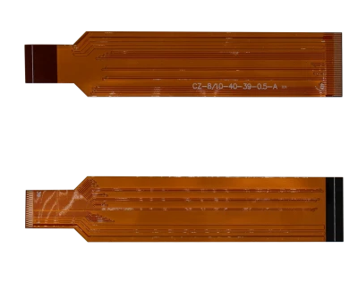 |
| 3A/3C/4SE | 15 pin to 40 pin FPC cable | 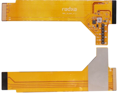 |
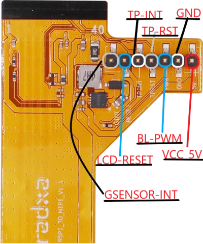
The 15-pin to 40-pin FPC cable has an additional 7-pin holder that needs to be connected as defined below:
Tutorials
- 4C+/5A/5B
- 3A/3C/4SE
- Raspberry Pi
Preparations
- ROCK 4C+/5A/5B SBC
The ROCK 5A is used here as a demonstration, and other boards operate in a similar way.
- Radxa Display 8 HD
- 39 pin to 40 pin FPC cable
- Power supply
Recommended Radxa PD 30W Adapter.
- Storage media with the latest official software of the corresponding product.
- USB to TTL serial cable or HDMI monitor and cable.
Procedures
-
Install the system disc storage media on the SBC
-
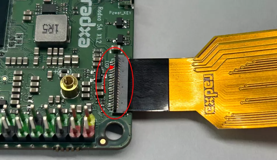
Connect the SBC and the display panel via the FPC cable. The 40 pin terminal is connected to the display panel: lift up the black tab on the FPC connector, insert the FPC cable into the connector, and press the black tab to secure the FPC cable.
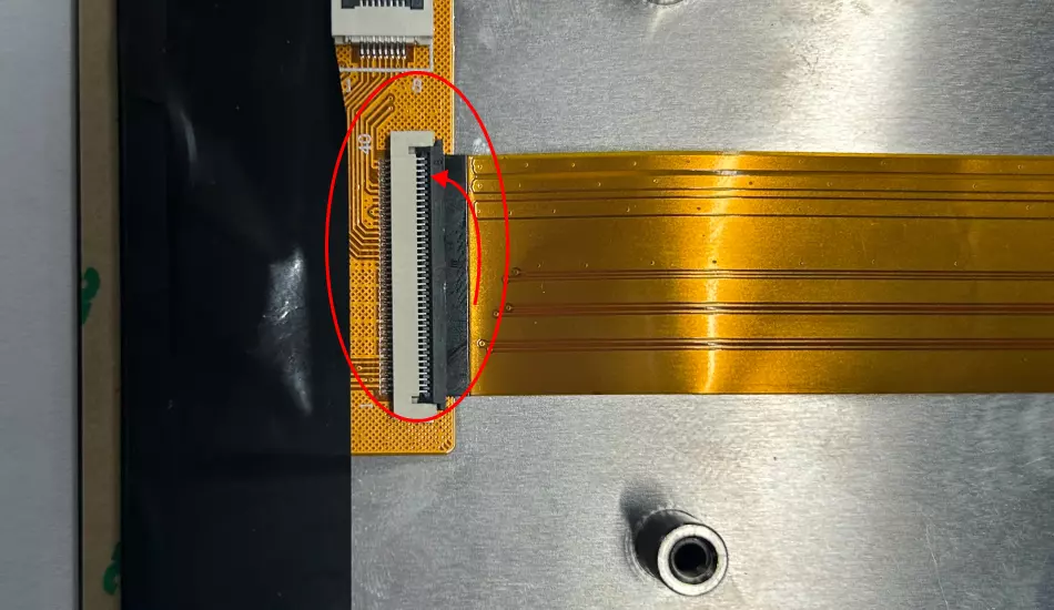 To connect the 39-pin end to the product's DSI connector: swivel up the black tab on the FPC connector, insert the FPC cable into the connector, and press down on the black tab to secure the FPC cable.
-
Connect the monitor or USB serial port debugging, power into the system
-
Enable the
Radxa Display 8 HDoverlay via the terminal. For the board-specific overlay steps, refer to: -
Reboot the SBC to apply overlay and the display will output a screen.
Ppreparations
- ROCK 3A/3C/4SE SBC
The ROCK 3C is used here as a demonstration, and other products operate in a similar manner.
- Radxa Display 8 HD
- 15 pin to 40 pin FPC cable
- Power supply
Recommended Radxa PD 30W Adapter.
- Storage media with the latest official software of the corresponding product.
- USB to TTL serial cable or HDMI monitor and cable.
Procedures
-
Install the system disc storage media on the SBC
-
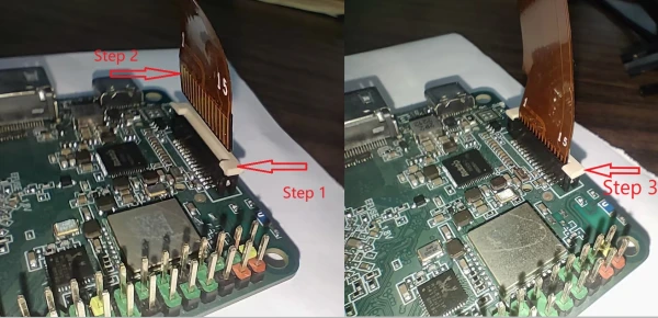
Connect the SBC and the display panel via the FPC cable. The 40 pin terminal is connected to the display panel: pull up the black module of the FPC connector on SBC, insert the FPC cable into the slot, and then press the black module to fix the FPC cable.
The 15 pin terminal is connected to the DSI connector on the SBC:
Step 1: lift up the white tab on the FPC connector
Step 2: Cable Gold Finger Back to White Snap Insert Connector
Step 3: Press the snap down firmly to fix the wires
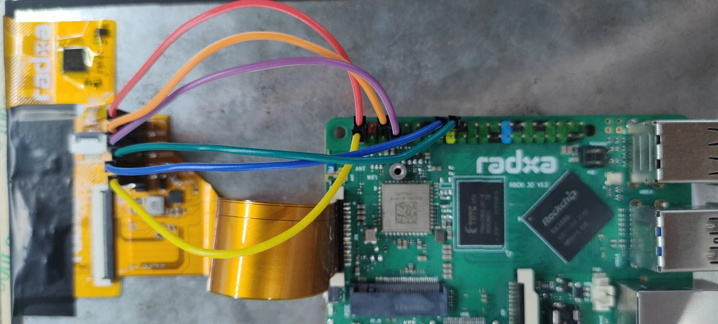
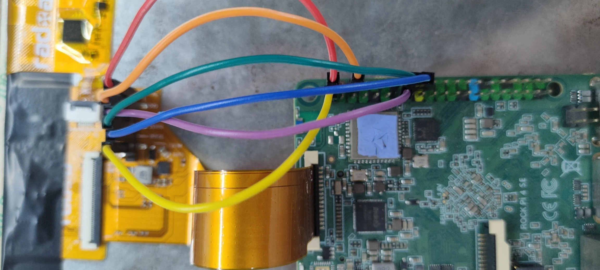
- The pins are connected to the GPIO socket of the SBC through the Dupont cable as follows:
- ROCK 3C
- ROCK 3A
- ROCK 4SE
| FPC cable header pin | SBC GPIO pin | |
|---|---|---|
| VCC_5V | <--> | +5.0V |
| GND | <--> | GND |
| PWM | <--> | PWM14_M0(GPIO Pin 7) |
| TP-RST | <--> | GPIO3_B2(GPIO Pin 18) |
| YP-INT | <--> | GPIO3_B1(GPIO Pin 16) |
| LCD-RST | <--> | +3.3V |
| GINT | <--> | None |
The physical connection diagram is referenced below:
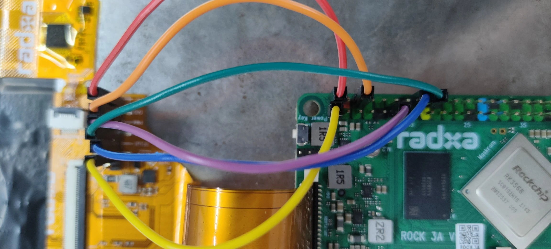
| FPC cable header pin | SBC GPIO pin | |
|---|---|---|
| VCC_5V | <--> | +5.0V |
| GND | <--> | GND |
| PWM | <--> | PWM14_M0(GPIO Pin 11) |
| TP-RST | <--> | GPIO3_B2(GPIO Pin 18) |
| YP-INT | <--> | GPIO0_B6(GPIO Pin 16) |
| LCD-RST | <--> | +3.3V |
| GINT | <--> | None |
The physical connection diagram is referenced below:
| FPC cable header pin | SBC GPIO pin | |
|---|---|---|
| VCC_5V | <--> | +5.0V |
| GND | <--> | GND |
| PWM | <--> | PWM1(GPIO Pin 13) |
| TP-RST | <--> | GPIO4_D2(GPIO Pin 16) |
| YP-INT | <--> | GPIO4_D4(GPIO Pin 18) |
| LCD-RST | <--> | +3.3V |
| GINT | <--> | None |
The physical connection diagram is referenced below:
-
Connect the monitor or USB serial port debugging, power into the system
-
Enable the
Radxa Display 8 HDoverlay via the terminal. For the board-specific overlay steps, refer to: -
Reboot the SBC to apply overlay and the display will output a screen.
Radxa Display 8 HD also works with Raspberry Pi 4B. The full guide is maintained in the radxa-displays-on-raspberry-pi repository.
Preparations
- Raspberry Pi 4B
- Radxa Display 8 HD panel
- 15-pin to 40-pin FPC cable
Hardware connection
Use the 15-pin to 40-pin FPC cable and connect the 7-pin holder to the Raspberry Pi 4B 40-pin GPIO as follows:
| Radxa Display 8 HD | Raspberry Pi 4B |
|---|---|
| VCC-5V | PIN 2: 5V Power |
| GND | PIN 6: GND |
| BL-PWM | PIN 1: 3V3 Power |
| TP-RST | PIN 11: GPIO 17 |
| TP-INT | PIN 7: GPIO 4 |
| LCD-RESET | PIN 17: 3V3 Power |
The seventh pin is currently unused.
Software settings
-
Install the required packages:
sudo apt update
sudo apt install dkms raspberrypi-kernel-headers -
Install the kernel driver (download from the releases page or use wget):
wget https://github.com/radxa/radxa-displays-on-raspberry-pi/releases/download/1.0.0/panel-radxa-dsi-dkms_1.0.0_all.deb
sudo dpkg -i panel-radxa-dsi-dkms_1.0.0_all.deb -
Modify the configuration file
/boot/firmware/config.txtand add the following lines after[all]:[all]
display_auto_detect=0
dtoverlay=vc4-kms-v3d
dtoverlay=vc4-kms-dsi-radxa-panel -
Save and reboot:
sync
sudo reboot
After restarting, the display should work normally.
For the latest instructions, please refer to the radxa-displays-on-raspberry-pi repository.