Other Interfaces
The Radxa CM4 IO Board provides multiple functional interfaces, allowing users to choose the features they need.
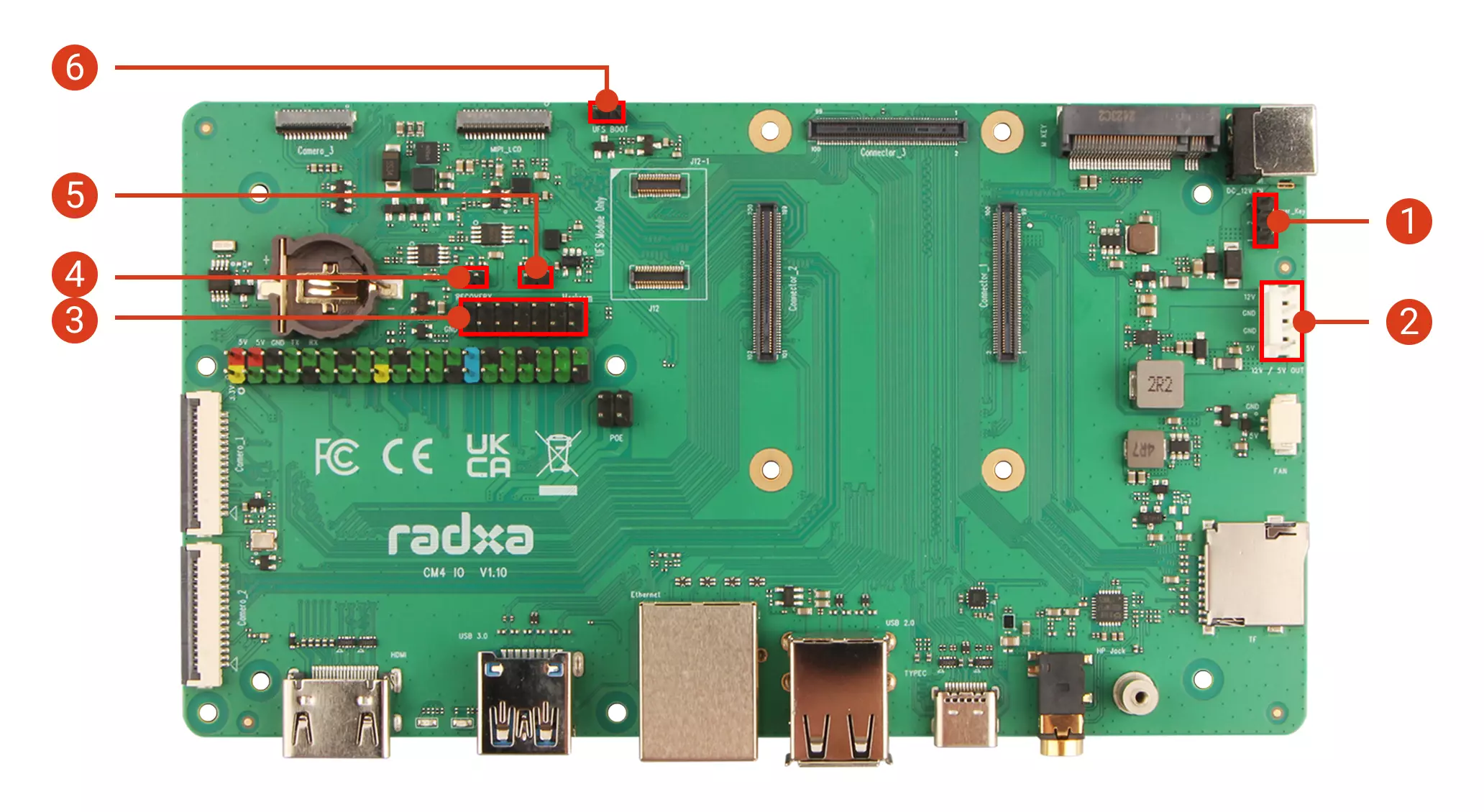
| No. | Description | No. | Description | No. | Description |
|---|---|---|---|---|---|
| ① | Power Header (for shutdown/reboot) | ③ | 14-pin GPIO Interface | ⑥ | UFS Module Boot Pins |
| ② | Power Output (GND / 5V / 12V) | ④ / ⑤ | Stereo Audio Output (for external speakers) |
Power Header
- Function Pin 1 : Power Button
- Function Pin 2 : GND
- Function Pin 3 : Reset Button
You can connect external buttons:
- Connect Function Pin 1 and Function Pin 2, then press and release to trigger shutdown.
- Connect Function Pin 2 and Function Pin 3, then press and release to trigger reboot.
Power Output
Provides 12V, 5V, and GND power outputs for powering other devices.
14-pin GPIO Interface
| Function2 | Function1 | Pin# | Pin# | Function1 | Function2 |
|---|---|---|---|---|---|
| GND | 1 | 2 | RECOVERY | ||
| GND | 3 | 4 | EEPROM_nWP | ||
| PDM1_CLK1_M1 | GPIO4_B0 | 5 | 6 | GPIO4_B2 | PDM1_SDI1_M1 |
| GND | 7 | 8 | GPIO3_D4 | UART5_RX_M0_1V8 | |
| UART5_TX_M0_1V8 | GPIO3_D5 | 9 | 10 | GND | |
| PDM1_SDI2_M1 | GPIO4_B1 | 11 | 12 | GND | |
| GND | 13 | 14 | MASKROM |
Stereo Audio Output
Stereo audio output interface for connecting external speakers.
UFS Module Boot Pins
Short the pins using a jumper cap or DuPont wires to use the UFS module as a system boot medium.
Interface Pin Definitions
For detailed pin definitions, please refer to the hardware schematics available on the Resource Download page.