40 Pin GPIO Interface
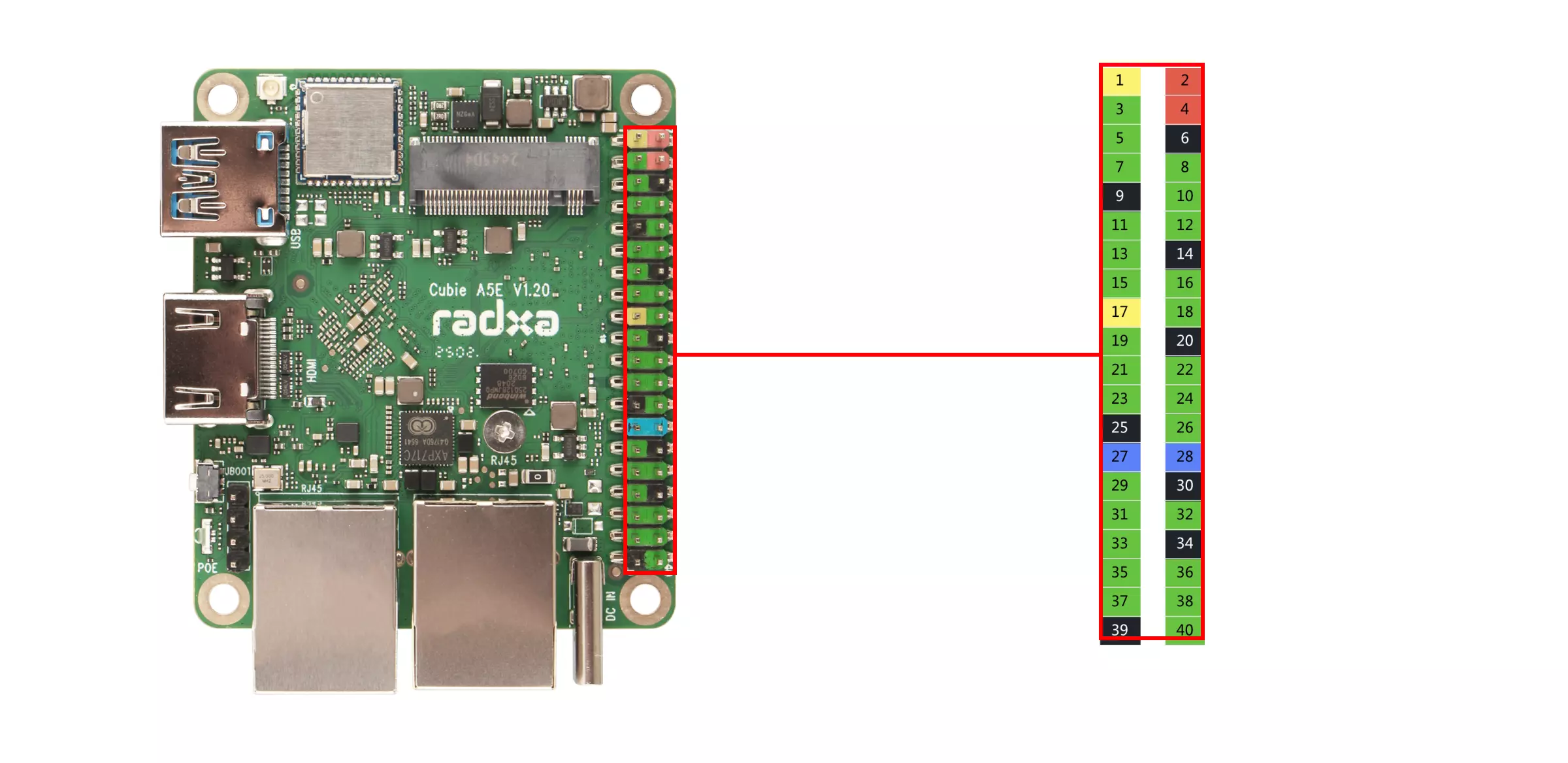
The Radxa Cubie A5E features an onboard 40-pin GPIO (General Purpose Input/Output) interface, providing highly flexible hardware expansion capabilities.
Users can connect various sensors, actuators, communication modules, displays, and other embedded peripherals through the 40-pin GPIO interface, enabling rapid prototyping and functional verification in fields such as IoT, robotics control, and industrial automation.
When using the 40-pin GPIO interface, please pay attention to pin connections and peripheral wiring. Ensure all connections are correct, as improper operation may cause hardware damage to the device.
GPIO Features
The Cubie A5E supports connecting external devices to its onboard GPIO pins, with support for UART, SPI, I2C, ADC, and more.
| Function7 | Function6 | Function5 | Function4 | Function3 | Function2 | Function1 | Pin# | Pin# | Function1 | Function2 | Function3 | Function4 | Function5 | Function6 | Function7 |
|---|---|---|---|---|---|---|---|---|---|---|---|---|---|---|---|
| +3.3V | 1 | 2 | +5.0V | ||||||||||||
| PB-EINT5 | HDMI-SDA | PWM0-9 | TRACE-CLK | I2S0-BCLK | TWI1-SDA | PB5 | 3 | 4 | +5.0V | ||||||
| PB-EINT4 | HDMI-SCL | PWM0-8 | TRACE-DATA2 | I2S0-MCLK | TWI1-SCK | PB4 | 5 | 6 | GND | ||||||
| PI-EINT7 | SPI2-CLK | PWM0-8 | UART4-CTS | UART6-RX | PI7 | 7 | 8 | PB9 | UARTO-TX | TWIO-SCK | TRACE-DATA1 | I2S0-DIN2 | I2S0-DOUBT2 | PB-EINT9 | |
| GND | 9 | 10 | PB10 | UARTO-RX | TWIO-SDA | PWM0-1 | I2S0-DIN3 | I2S0-DOUBT3 | PB-EINT10 | ||||||
| PI-EINT9 | PWM0-10 | DMIC-DATA2 | TWI5-SDA | PI9 | 11 | 12 | PI2 | UART5-TX | SPI1-CSO | PWM0-3 | I2S2-BCLK | I2S2-BCLK | PI-EINT2 | ||
| PI-EINT10 | I2S2-MCLK | PWM0-11 | DMIC-DATA1 | OWA-OUT | PI10 | 13 | 14 | GND | |||||||
| S-PL-EINT12 | S-SPI0-MOSI | DMIC-DATA2 | S-UART0-TX | MCU-PWM0-6 | S-TWI2-SCK | PL12 | 15 | 16 | PI11 | UART3-TX | DMIC-DATA0 | PWM0-12 | PI-EINT11 | ||
| +3.3V | 17 | 18 | PI14 | UART6-RTS | DMIC-CLK | PWM0-15 | PI-EINT14 | ||||||||
| SPI1-MOSI | PI-EINT13 | PWM0-4 | UART7-TX | TWI4-SCK | PB13 | 19 | 20 | GND | |||||||
| PB-EINT14 | PWM0-5 | SPI1-MISO | UART7-RX | TWI4-SDA | PB14 | 21 | 22 | PL13 | S-TWI2-SDA | MCU-PWM0-7 | S-UARTO-RX | DMIC-DATA3 | S-SPI-MISO | S-PL-EINT13 | |
| PB-EINT12 | PWM0-3 | SPI1-CLK | UART7-CTS | TWI5-SDA | PB12 | 23 | 24 | PB11 | TWI5-SCK | UART7-RTS | PWM0-2 | SPI1-CSO | PB-EINT11 | ||
| GND | 25 | 26 | PI0 | TWI4-SCK | UART4-TX | PWM0-1 | I2S2-DIN3 | I2S2-DOUBT3 | PI-EINTO | ||||||
| (USB2-DM) | PI-EINT16 | PWM1-1 | TWI2-SDA | UART3-CTS | PI16 | 27 | 28 | PI15 | TWI2-SCK | UART3-RTS | PWM1-0 | PI-EINT15 | (USB2-DM) | ||
| PI-EINT8 | SPI2-MOSI | PWM0-9 | IR-RX | TWI5-SCK | PI8 | 29 | 30 | GND | |||||||
| PI-EINT12 | SPI2-MISO | PWM0-13 | UART3-RX | PI12 | 31 | 32 | PI1 | TWI4-SDA | UART4-RX | PWM0-2 | I2S2-DIN2 | I2S2-DOUBT2 | PI-EINT1 | ||
| PI-EINT6 | SPI2-CSO | PWM0-7 | UART6-TX | UART4-RTS | PI6 | 33 | 34 | GND | |||||||
| PI-EINT13 | I2S2-MCLK | PWM0-14 | DMIC-DATA3 | UART6-CTS | PI13 | 35 | 36 | PI3 | UART5-RX | PWM0-4 | I2S2-LRCK | SPI1-CLK | PI-EINT3 | ||
| GPADC2 | 37 | 38 | PI5 | UART5-CTS | SPI1-MISO | PWM0-6 | I2S2-DINO | I2S2-DOUBT1 | PI-EINT5 | ||||||
| GND | 39 | 40 | PI4 | UART5-RTS | SPI1-MOSI | PWM0-5 | I2S2-DOUBT0 | I2S2-DIN1 | PI-EINT4 |
GPIO Pin Numbering
To control a specific pin, you need to calculate the pin number using the following formula:
| GPIO Chip | Pin Number | Calculation Formula |
|---|---|---|
| GPIOCHIP1 | A ~ K | NUM + 32 * (A ~ K) |
| GPIOCHIP0 | L ~ | NUM + 32 * (L ~ ) |
Calculation Example:
- PI4
GPIOCHIP1 -> 4 + 32 * (A ~ K) -> 4 + 32 * 8 -> 260
GPIO Usage
Through the 40-Pin GPIO interface on the board, demonstrate common GPIO usage.
Install python-periphery
Use python-periphery library to control GPIO pins.
sudo pip3 install python-periphery
GPIO Input
Hardware Preparation
- Board
- Dupont wire
Software Preparation
Test Code
The following code uses the python-periphery library to read the high and low level of the PI4 pin.
gpio_input.py
from periphery import GPIO
import time

def read_gpio_input():
    # Configure GPIO input (modify pin number according to actual hardware)
    # Using pin 260 of /dev/gpiochip1 here (corresponds to PI4)
    try:
        # Initialize GPIO in input mode
        gpio_in = GPIO("/dev/gpiochip1", 260, "in")

        print("Starting GPIO input reading (press Ctrl+C to exit)")
        while True:
            # Read pin value
            value = gpio_in.read()
            print(f"GPIO input value: {value} (True=High, False=Low)")
            time.sleep(1)  # Read once per second

    except KeyboardInterrupt:
        print("\nProgram exited")
    except Exception as e:
        print(f"Error occurred: {e}")
    finally:
        # Ensure resources are released
        try:
            gpio_in.close()
        except:
            pass

if __name__ == "__main__":
    read_gpio_input()
Test Steps
-
Connect the PI4 pin to the GND or 3.3V pin
-
Save the code as
gpio_input.py -
Run the test code using
sudo python3 gpio_input.py
Experimental Phenomenon
Terminal will output False or True information.
False represents low level, True represents high level.
GPIO Output
Hardware Preparation
- Board
- Dupont wire
Software Preparation
Test Code
The following code uses the python-periphery library to control PI4 pin output high and low level, then read the high and low level of PI4 pin through PI5 pin.
gpio_output.py
from periphery import GPIO
import time

def gpio_output_with_feedback():
    # GPIO Configuration (modify pin numbers based on your hardware)
    # PI4 (output) → maps to pin 260 of /dev/gpiochip1
    # PI5 (input)  → maps to pin 261 of /dev/gpiochip1
    OUTPUT_PIN_CHIP = "/dev/gpiochip1"
    OUTPUT_PIN_NUMBER = 260  # PI4 (output pin, controlled by the script)
    INPUT_PIN_NUMBER = 261   # PI5 (input pin, reads PI4's output state)

    # Initialize GPIO objects as None first (for safe release later)
    gpio_out = None
    gpio_in = None

    try:
        # Initialize PI4 as OUTPUT mode
        gpio_out = GPIO(OUTPUT_PIN_CHIP, OUTPUT_PIN_NUMBER, "out")
        # Initialize PI5 as INPUT mode
        gpio_in = GPIO(OUTPUT_PIN_CHIP, INPUT_PIN_NUMBER, "in")

        # Print test initialization info
        print("=== GPIO Output-Input Feedback Test Started ===")
        print(f"Controlled Pin (PI4): {OUTPUT_PIN_CHIP} - Pin {OUTPUT_PIN_NUMBER} (OUTPUT)")
        print(f"Monitoring Pin (PI5): {OUTPUT_PIN_CHIP} - Pin {INPUT_PIN_NUMBER} (INPUT)")
        print("Test Behavior: PI4 toggles HIGH/LOW every 1s; PI5 verifies PI4's state")
        print("Press Ctrl+C to stop the test\n")

        # Main loop: Toggle PI4 and read PI5 feedback
        while True:
            # 1. Set PI4 to HIGH level
            gpio_out.write(True)
            time.sleep(0.1)  # Short delay for signal stabilization (avoid read lag)
            pi5_reading = gpio_in.read()
            print(f"PI4 Output: HIGH (True) | PI5 Reading: {pi5_reading}")

            # Keep PI4 HIGH for 1 second
            time.sleep(1)

            # 2. Set PI4 to LOW level
            gpio_out.write(False)
            time.sleep(0.1)  # Short delay for signal stabilization
            pi5_reading = gpio_in.read()
            print(f"PI4 Output: LOW (False) | PI5 Reading: {pi5_reading}")

            # Keep PI4 LOW for 1 second
            time.sleep(1)

    # Handle user-initiated exit (Ctrl+C)
    except KeyboardInterrupt:
        print("\n\nTest stopped by user (Ctrl+C)")
    # Handle other unexpected errors (e.g., GPIO access failure)
    except Exception as e:
        print(f"\nError during test: {str(e)}")
    # Ensure GPIO resources are released even if an error occurs
    finally:
        print("\nReleasing GPIO resources...")
        # Safely close PI4 (set to LOW first to avoid residual high level)
        if gpio_out:
            try:
                gpio_out.write(False)
                gpio_out.close()
                print(f"Successfully closed PI4 (Pin {OUTPUT_PIN_NUMBER})")
            except Exception as close_err:
                print(f"Failed to close PI4 (Pin {OUTPUT_PIN_NUMBER}): {str(close_err)}")
        # Safely close PI5
        if gpio_in:
            try:
                gpio_in.close()
                print(f"Successfully closed PI5 (Pin {INPUT_PIN_NUMBER})")
            except Exception as close_err:
                print(f"Failed to close PI5 (Pin {INPUT_PIN_NUMBER}): {str(close_err)}")
        print("Resource release complete.")

# Run the test when the script is executed directly
if __name__ == "__main__":
    gpio_output_with_feedback()
Test Steps
-
Short the PI4 pin and PI5 pin
-
Save the code as
gpio_output.py -
Run the test code using
sudo python3 gpio_output.py
Experimental Phenomenon
Terminal will output False or True information.
False represents low level, True represents high level.
PWM Output
Hardware Preparation
- Board
- LED
- Dupont wire
Software Preparation
Test Code
The following code uses the python-periphery library to test PWM output.
pwm_output.py
from periphery import PWM
import time

def pwm_test():
    try:
        # Configure PWM parameters - modify according to your hardware
        # Common PWM paths: /sys/class/pwm/pwmchip0/pwm0, etc.
        PWM_CHIP = 0        # PWM chip number
        PWM_CHANNEL = 7     # PWM channel number

        # Initialize PWM
        pwm = PWM(PWM_CHIP, PWM_CHANNEL)

        print(f"PWM Test: Using PWM{PWM_CHIP}.{PWM_CHANNEL} (Pin: PI6)")

        # Set PWM frequency to 1kHz
        frequency = 1000  # 1000 Hz
        pwm.frequency = frequency
        print(f"  Set frequency: {frequency} Hz")

        # Enable PWM output
        pwm.enable()
        print("  PWM enabled")

        # Test different duty cycles (0% to 100%)
        duty_cycles = [0.0, 0.25, 0.5, 0.75, 1.0]

        for duty in duty_cycles:
            pwm.duty_cycle = duty
            print(f"  Set duty cycle: {duty*100:.1f}%")
            time.sleep(1)  # Maintain current duty cycle for 1 second

        # Cleanup
        pwm.disable()
        pwm.close()
        print("  PWM disabled and closed")
        print("PWM Test completed successfully")

    except Exception as e:
        print(f"PWM Test failed: {e}")

if __name__ == "__main__":
    print("Starting PWM Signal Test...\n")
    pwm_test()
Test Steps
-
Enter
rsetup->Overlay->Manage overlaysand check theEnable PWM0-7option, then restart the system -
Connect the positive terminal of the LED to the PI6 pin
-
Connect the negative terminal of the LED to the GND pin
-
Save the code as
pwm_output.py -
Run the test code using
sudo python3 pwm_output.py
Experimental Phenomenon
The external LED will flash with different brightness, from bright to dark.
UART Usage
UART (Universal Asynchronous Receiver/Transmitter) is a widely used serial communication protocol, used for asynchronous serial data transmission between embedded systems, computers, and peripherals.
Hardware Preparation
- Board
- Dupont wire
Software Preparation
Test Code
The following code uses the python-periphery library to test UART4 loopback communication.
uart_example.py
from periphery import Serial
import time

def uart_test():
    try:
        # Modify the serial device path according to your hardware, common paths include /dev/ttyS0, /dev/ttyS1, /dev/ttyUSB0, etc.
        # PI11(TX)  PI31(RX)
        UART_DEVICE = "/dev/ttyAS3"
        BAUDRATE = 115200

        # Initialize serial port
        serial = Serial(UART_DEVICE, BAUDRATE)

        print(f"UART Test: Opening serial port {UART_DEVICE}, baud rate {BAUDRATE}")

        # Send test data
        test_message = "Hello, UART Test!\n"
        serial.write(test_message.encode())
        print(f"  Sent data: {test_message.strip()}")

        # Wait for data transmission
        time.sleep(0.1)

        # Try to read data (if loopback or other device responds)
        if serial.input_waiting() > 0:
            received_data = serial.read(serial.input_waiting())
            print(f"  Received data: {received_data.decode().strip()}")
        else:
            print("  No data received (normal unless loopback is connected)")

        serial.close()
        print("UART test completed")

    except Exception as e:
        print(f"UART test failed: {e}")

if __name__ == "__main__":
    uart_test()
Test Steps
-
Enter
rsetup->Overlay->Manage overlaysand check theEnable UART3option, then restart the system -
Short the PI11 pin and PI31 pin
-
Save the code as
uart_example.py -
Run the test code using
sudo python3 uart_example.py
Experimental Phenomenon
Terminal will output sent and received information, and you can judge whether the UART loopback test is successful based on the terminal output information.
I2C Usage
I2C (Inter-Integrated Circuit) is a widely used synchronous serial communication protocol developed by Philips (now NXP), mainly used for short-distance chip-to-chip communication.
Hardware Preparation
- Board
- I2C device (e.g., OLED display, its corresponding I2C address is 0x3C)
- Dupont wire
Software Preparation
Test Code
The following code uses the python-periphery library to test I2C communication.
i2c_example.py
from periphery import I2C

def i2c_device_detection():
    """I2C Test - Check if device exists
    Pin reference: PB5 (SDA), PB4 (SCL)
    """
    # Modify according to your hardware connection
    # Common I2C bus devices: /dev/i2c-0, etc.
    I2C_BUS = "/dev/i2c-1"
    TARGET_ADDR = 0x3C  # Target address to check

    i2c = None  # Initialize I2C object reference
    try:
        # Initialize I2C object
        i2c = I2C(I2C_BUS)

        # Attempt a simple read/write operation to detect device
        # Sending a single 0x00 byte as test communication
        msgs = [I2C.Message([0x00])]
        i2c.transfer(TARGET_ADDR, msgs)

        print(f"I2C Test: Device found at address 0x{TARGET_ADDR:02X}")
        return True

    except Exception as e:
        # Exception (e.g., IOError) usually indicates no device or no response
        print(f"I2C Test: No device or no response at address 0x{TARGET_ADDR:02X}: {e}")
        return False
    finally:
        # Ensure I2C resources are released
        if i2c is not None:
            try:
                i2c.close()
            except:
                pass

if __name__ == "__main__":
    print("Starting I2C Device Detection...")
    i2c_device_detection()
    print("I2C Test completed")
Test Steps
-
Enter
rsetup->Overlay->Manage overlaysand check theEnable TWI1option, then restart the system -
Connect the SCL pin of the OLED display to the PB4 pin, connect the SDA pin of the OLED display to the PB5 pin, connect the VCC to 5V, and connect the GND to GND
-
Save the code as
i2c_example.py -
Run the test code using
sudo python3 i2c_example.py
Experimental Phenomenon
The script function is to check if there is an I2C device that can respond to the specified I2C bus address, which can be used to determine if the I2C device is working normally.
SPI Usage
SPI (Serial Peripheral Interface) is a high-speed, full-duplex, synchronous serial communication protocol developed by Motorola (now NXP), mainly used for short-distance chip-to-chip communication, commonly used in sensor, storage (like Flash), display, etc. device data transmission between microcontrollers.
Hardware Preparation
- Board
- Dupont wire
Software Preparation
Test Code
The following code uses the python-periphery library to test SPI loopback communication.
spi_example.py
from periphery import SPI

def spi_communication_test():
    # Data to be transmitted (4 bytes)
    transmit_data = [0xAA, 0xBB, 0xCC, 0xDD]

    try:
        # Initialize SPI resource
        # Parameters: SPI device path, mode 0, 1MHz clock frequency
        spi = SPI("/dev/spidev1.0", 0, 1000000)

        # Transmit data and receive response simultaneously
        # SPI is full-duplex, so data is sent and received at the same time
        received_data = spi.transfer(transmit_data)

        # Print test results
        print("SPI Test:")
        print("  Transmitted data: [0x{:02x}, 0x{:02x}, 0x{:02x}, 0x{:02x}]".format(*transmit_data))
        print("  Received data:    [0x{:02x}, 0x{:02x}, 0x{:02x}, 0x{:02x}]".format(*received_data))

    except Exception as e:
        print(f"SPI Test failed: {e}")
    finally:
        # Ensure SPI resource is released
        try:
            spi.close()
        except:
            pass

if __name__ == "__main__":
    print("Starting SPI Communication Test...\n")
    spi_communication_test()
    print("\nSPI Test completed")
Test Steps
-
Enter
rsetup->Overlay->Manage overlaysand check theEnable spidev on SPI1option, then restart the system -
Connect the PI4 pin and PI5 pin
-
Save the code as
spi_example.py -
Run the test code using
sudo python3 spi_example.py
Experimental Phenomenon
Terminal will output sent and received information, and you can judge whether the SPI loopback test is successful based on the terminal output information.