Hardware interfaces
This page introduces the Cubie A7S hardware interfaces.
Block diagram
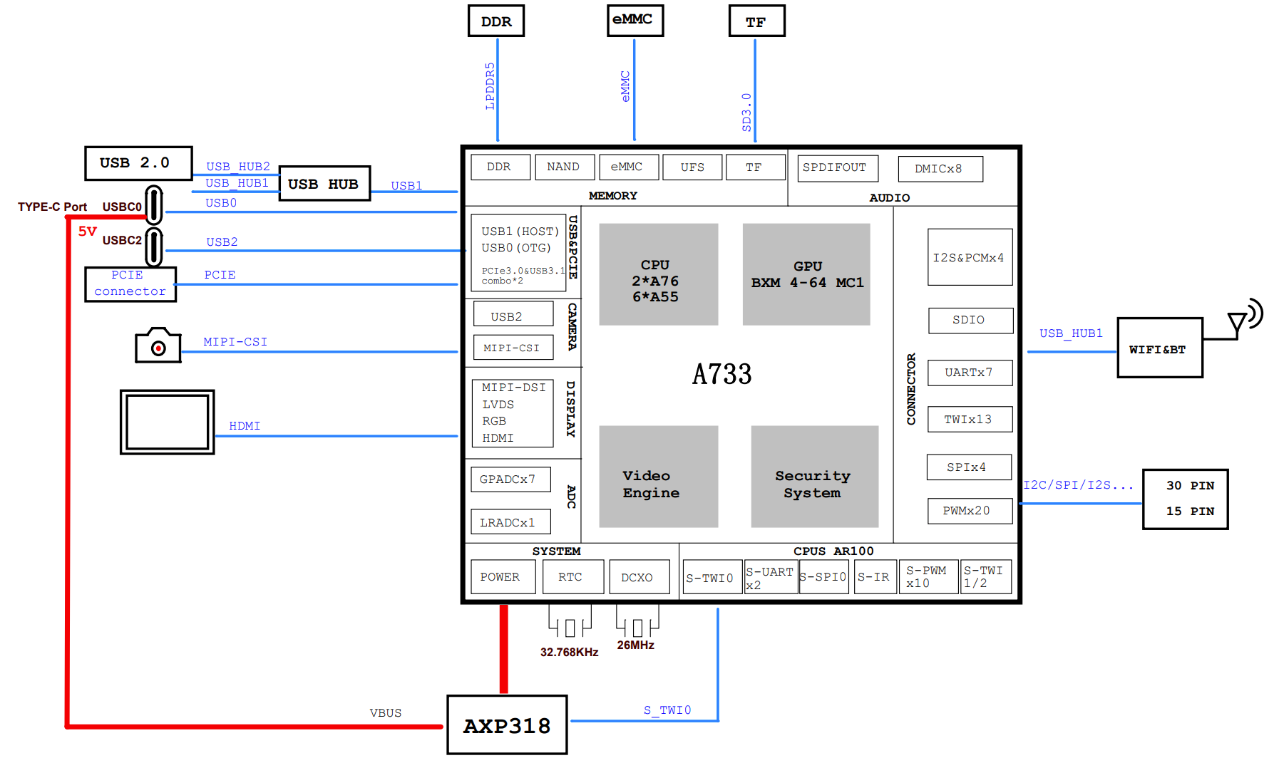
Interface overview
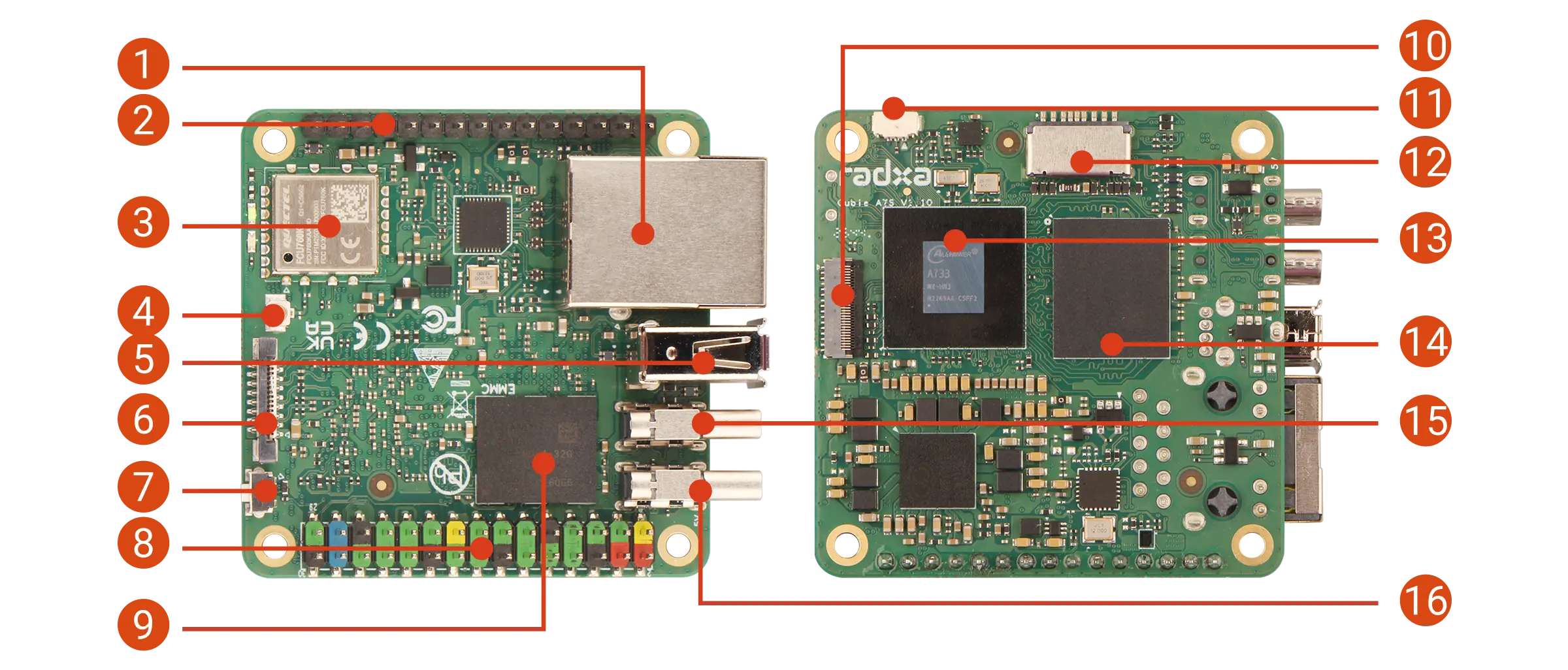
| No. | Description | No. | Description | No. | Description |
|---|---|---|---|---|---|
| 1 | Gigabit Ethernet | 2 | 15‑pin GPIO header | 3 | Wi‑Fi 6 & BT 5.4 module |
| 4 | Antenna connector | 5 | USB 2.0 Type‑A | 6 | FPC connector - PCIe 3.0 x1, NVMe SSD expansion |
| 7 | USB BOOT button | 8 | 30‑pin GPIO header | 9 | Onboard eMMC |
| 10 | MIPI CSI camera connector | 11 | Fan header | 12 | microSD slot |
| 13 | Allwinner A733 | 14 | LPDDR5 | 15 | USB‑C 2 - USB 3.2, DP Alt Mode and OTG |
| 16 | USB‑C 1 - 5V power input and OTG |
If you purchased a Cubie A7S variant without onboard eMMC, the eMMC footprint on the board will be unpopulated.
Gigabit Ethernet
Cubie A7S has one Gigabit Ethernet port for wired networking, supporting 10/100/1000 Mbps auto-negotiation.
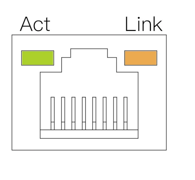
| LED | State | Description |
|---|---|---|
| Orange | On | Link up (connected) |
| Green | Blinking | Data activity |
| Off | - | No link (cable unplugged or network issue) |
WiFi & BT
Cubie A7S includes one Wi‑Fi 6 & BT 5.4 module, supporting dual-band 2.4GHz/5GHz Wi‑Fi and Bluetooth 5.4.
Antenna connector
Cubie A7S includes one antenna connector for an external antenna to improve wireless signal strength.
USB
Cubie A7S includes one USB 2.0 Type‑A port, one USB 2.0 Type‑C port (USB‑C1), and one USB 3.2 Type‑C port (USB‑C2).
- USB 2.0 Type‑A: connect USB 2.0 devices such as mouse, keyboard, or USB flash drive.
- USB 2.0 Type‑C (USB‑C1): supports 5V power input and OTG.
- USB 3.2 Type‑C (USB‑C2): supports DisplayPort Alt Mode and OTG.
30-pin GPIO header
| FUNC9 | FUNC8 | FUNC7 | FUNC6 | FUNC5 | FUNC4 | FUNC3 | FUNC2 | FUNC1 | Pin# | Pin# | FUNC1 | FUNC2 | FUNC3 | FUNC4 | FUNC5 | FUNC6 | FUNC7 | FUNC8 | FUNC9 |
|---|---|---|---|---|---|---|---|---|---|---|---|---|---|---|---|---|---|---|---|
| +3.3V | 1 | 2 | +5.0V | ||||||||||||||||
| TWI11-SDA | TWI3-SDA | TWI7-SDA | UART2-CTS | UART3-RX | PWM1-5 | PJ23 | 3 | 4 | +5.0V | ||||||||||
| TWI11-SCK | TWI3-SCK | TWI7-SCK | UART2-RTS | UART3-TX | PWM1-4 | PJ22 | 5 | 6 | GND | ||||||||||
| PB-EINT0 | JTAG-MS | LCD0-D0 | DSI-TRIG-LCD-TE1 | UART0-TX | UART2-TX | PB0 | 7 | 8 | PB9 | UART0-TX | PWM1-1 | WATCHDOG-SIG | LCD0-D16 | TWI8-SCK | TWI0-SCK | PB-EINT9 | |||
| GND | 9 | 10 | PB10 | UART0-RX | PWM1-2 | PLL-LOCK-DBG | LCD0-D17 | TWI8-SDA | TWI0-SDA | PB-EINT10 | |||||||||
| PB-EINT1 | JTAG-CK | LCD0-D1 | UART0-RX | UART2-RX | PB1 | 11 | 12 | PB5 | PWM0-1 | LCD0-D17 | TRACE-DATA0 | PB-EINT5 | |||||||
| PL-EINT6 | S-PWM0-4 | S-IR-RX | S-UART0-TX | S-JTAG-DO | PL6 | 13 | 14 | GND | |||||||||||
| PL-EINT7 | S-PWM0-5 | S-UART0-RX | S-JTAG-DI | PL7 | 15 | 16 | PJ24 | PWM1-6 | UART4-TX | TWI4-SCK | PJ-EINT24 | ||||||||
| +3.3V | 17 | 18 | PJ25 | PWM1-7 | UART4-RX | TWI4-SDA | PJ-EINT25 | ||||||||||||
| LVDS1-D1P | DSI1-D1P | EINK-D12 | SPI1-MOSI <DBI-SDO> | PWM1-2 | PD-EINT12 | PD12 | 19 | 20 | GND | ||||||||||
| LVDS1-D1N | DSI1-D1N | EINK-D13 | SPI1-MISO <DBI-SDI/DBI-TE/DBI-DCX> | PWM1-3 | PD-EINT13 | PD13 | 21 | 22 | PL5 | S-JTAG-CK | S-PWM0-3 | PL-EINT5 | |||||||
| LVDS1-D0N | DSI1-D0N | EINK-D11 | SPI1-CLK <DBI-SCLK> | PWM1-1 | PD-EINT11 | PD11 | 23 | 24 | PD10 | LCD0-D14 | LVDS1-D0P | DSI1-D0P | EINK-D10 | SPI1-CS0<DBI-CSX> | PWM1-0 | PD-EINT10 | |||
| GND | 25 | 26 | PD14 | LCD0-D20 | EINK-D14 | SPI1-HOLD<DBI-DCX/DBI-WRX> | UART3-RTS | PD-EINT14 | |||||||||||
| LVDS1-CKN | DSI1-D2N | EINK-LEH | TWI2-SDA | UART3-RX | PD-EINT17 | PD17 | 27 | 28 | PD16 | LCD0-D22 | LVDS1-CKP | DSI1-D2P | EINK-OEH | TWI2-SCK | UART3-TX | PD-EINT16 | |||
| UART2-RTS | HDMI-SCL | LCD0-D8 | JTAG-DO | TWI0-SCK | PB-EINT2 | PB2 | 29 | 30 | GND |
15-pin GPIO header
| Pin# | FUNC1 | FUNC2 | FUNC3 | FUNC4 | FUNC5 | FUNC6 |
|---|---|---|---|---|---|---|
1 | PB3 | HDMI-SDA | LCD0-D9 | PB-EINT3 | ||
2 | PM3 | S-UART0-RX | S-UART1-RX | S-PWM0-5 | PM-EINT3 | |
3 | PM4 | S-UART0-TX | S-UART1-TX | S-PWM0-0 | S-IR-RX | PM-EINT4 |
4 | GND | |||||
5 | PB6 | PWM0-2 | PWM0-8 | TRACE-DATA1 | PB-EINT6 | |
6 | PB4 | PWM0-0 | HDMI-CEC | LCD0-D16 | TRACE-CLK | PB-EINT4 |
7 | PB8 | PWM1-0 | OWA0-OUT | TRACE-DATA3 | PB-EINT8 | |
8 | PB7 | PWM0-9 | OWA0-IN | TRACE-DATA2 | PB-EINT7 | |
9 | GND | |||||
10 | PG0 | SDC1-CLK | LCD0-D0 | PWM1-1 | LPC-LAD0 | PG-EINT0 |
11 | PG1 | SDC1-CMD | LCD0-D1 | PWM1-2 | LPC-LPME | PG-EINT1 |
12 | PG2 | SDC1-D0 | LCD0-D8 | PWM1-3 | LPC-LPCPD | PG-EINT2 |
13 | PG3 | SDC1-D1 | LCD0-D9 | PWM1-4 | LPC-LFRAME | PG-EINT3 |
14 | PG4 | SDC1-D2 | LCD0-D16 | PWM1-5 | LPC-LSMI | PG-EINT4 |
15 | PG5 | SDC1-D3 | LCD0-D17 | PWM1-6 | LPC-LCLK | PG-EINT5 |
FPC connector
Cubie A7S includes one FPC connector for high-speed expansion, supporting PCIe 3.0 x1 and NVMe SSD expansion.
Status LEDs
Cubie A7S includes one power LED and one status LED.
- Power LED: solid green indicates normal power.
- Status LED: blinking blue indicates the system is booting/running.
USB BOOT button
Cubie A7S includes a USB BOOT button used to enter FEL mode.
FEL is a low-level boot and flashing mode on Allwinner SoCs, mainly used for recovery or debugging when the device cannot boot from normal storage.
- Enter FEL mode
Before powering on, press and hold the Cubie A7S USB BOOT button. Power on the board, then release the button to enter FEL mode.
Fan header
Cubie A7S includes one 3‑Pin fan header for active cooling with PWM speed control.
Key specifications:
- Interface type: 3‑Pin female header, 0.8mm pin spacing
- Operating voltage: 5V (VCC5V0_SYS)
- Speed control: PWM (no tachometer feedback)
- PWM signal: PJ27_PWM1-9
For detailed pin definitions and usage instructions, see the Fan Interface tutorial (note: the triangle silkscreen marking points to pin 1).
MIPI camera connector
Cubie A7S includes one 4‑lane MIPI camera connector for connecting a MIPI camera module.
MIPI CSI connector specs:
- Connector type: 31‑pin 0.3 mm pitch SMD horizontal FPC connector
- Connection type: Flip type, bottom contact
microSD slot
Cubie A7S includes one microSD slot compatible with microSD / microSDHC / microSDXC cards, used for OS boot and/or storage expansion.
We recommend a 32GB or larger microSD card.
Onboard eMMC (optional)
If your board includes onboard eMMC, you can use it as a boot device or for additional storage.
Compared to microSD cards, eMMC typically offers higher read/write performance and can improve boot and system responsiveness.