Hardware Information
System Block Diagram
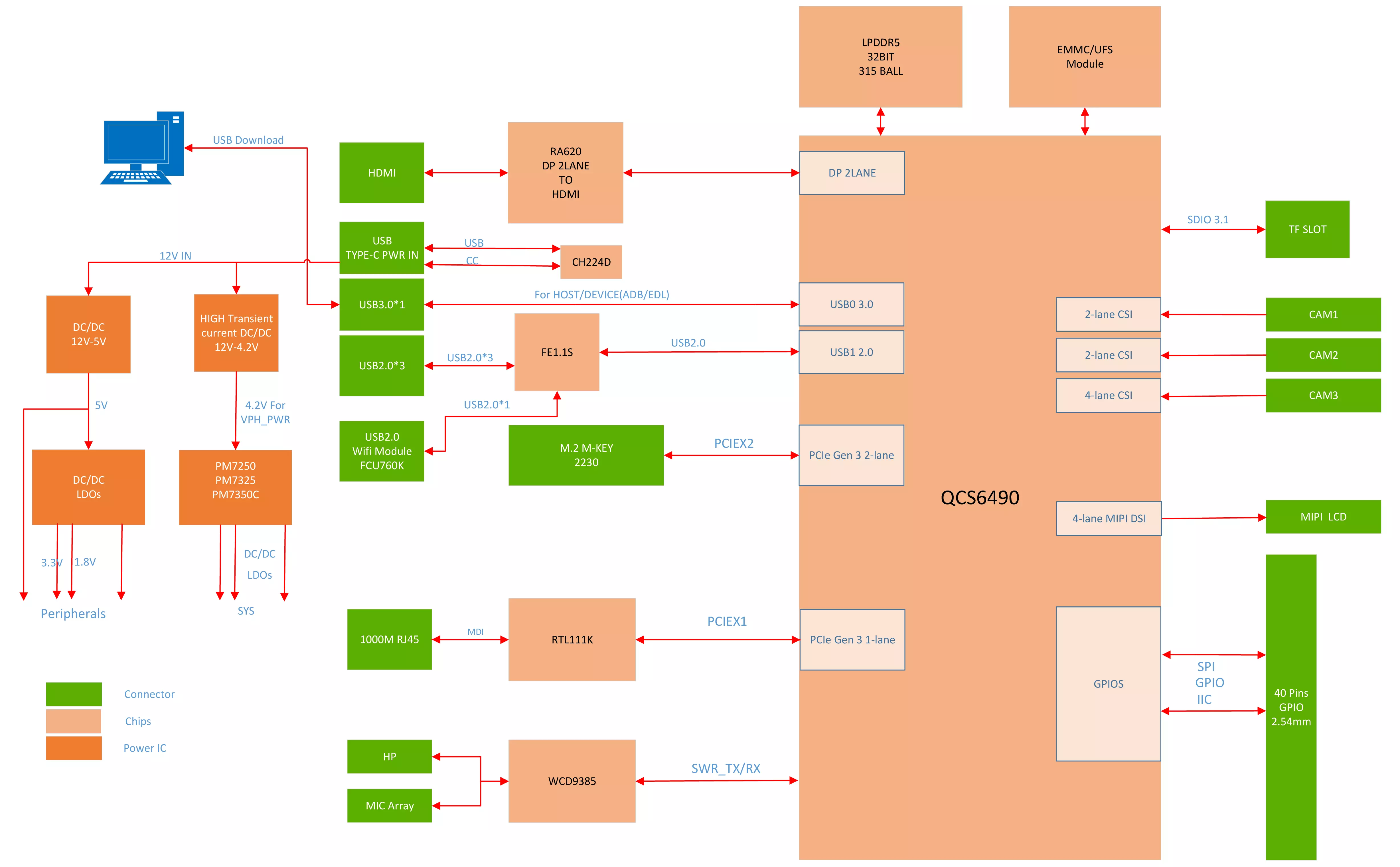
Interface Description
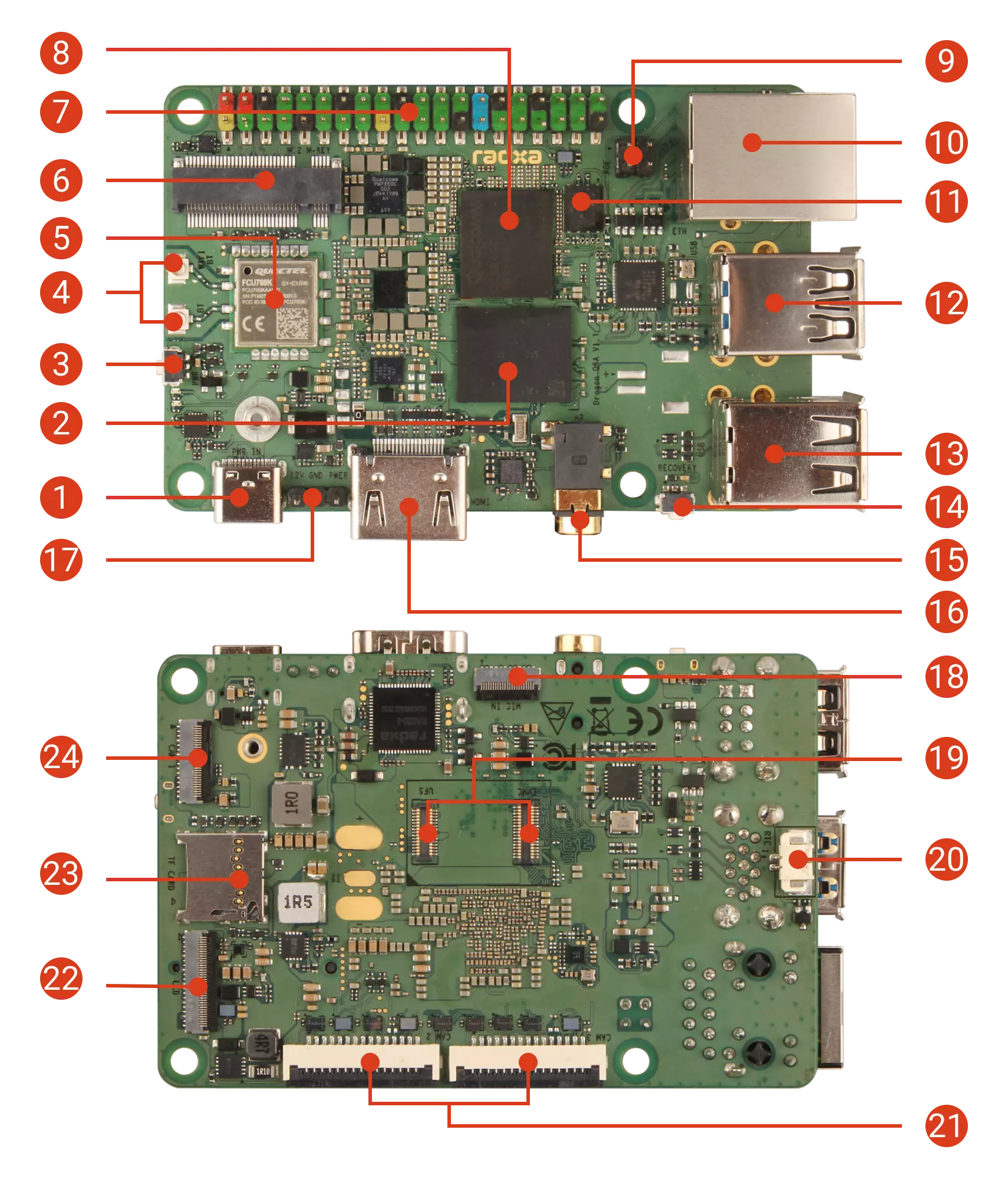
| No. | Description | No. | Description | No. | Description |
|---|---|---|---|---|---|
| 1 | Qualcomm QCS6490 | 2 | 40-Pin GPIO Header | 3 | M.2 M Key slot |
| 4 | WiFi 6 / BT 5.4 | 5 | Antenna connector | 6 | Power button |
| 7 | User LED | 8 | Power LED | 9 | Type-C power input |
| 10 | Power input header | 11 | MIPI CSI (4 Lane) | 12 | microSD card slot |
| 13 | MIPI DSI (4 Lane) | 14 | PoE header | 15 | Gigabit Ethernet |
| 16 | QSPI Nor Flash | 17 | USB ports USB 2.0 Type-A (upper) / USB 3.1 OTG Type-A (lower) | 18 | LPDDR5 memory |
| 19 | 2x USB 2.0 Type-A ports | 20 | EDL button | 21 | Headphone jack |
| 22 | Standard HDMI | 23 | eMMC & UFS module connector | 24 | RTC battery connector |
| 25 | 2x MIPI CSI (2 Lane) |
Power Input Header Pinout
No. 10 is the 12V external power input interface, a 3-pin header with the following pin functions:
| Pin | Definition |
|---|---|
| 1 | 12V |
| 2 | GND |
| 3 | PWR |
External power supply
Connect the positive and negative terminals of the 12V power supply to the 12V and GND pins on the Dragon Q6A to power it.
danger
Please do not connect the power supply incorrectly or in reverse, as improper operation may cause hardware damage.
External power button
By default, when the Dragon Q6A is powered off, briefly short the PWR and GND pins to start it; when the Dragon Q6A is powered on, briefly short the PWR and GND pins to bring up the shutdown menu.