Android 15
The Radxa Dragon Q6A's Android 15 system requires flashing BIOS firmware to boot, and the system boot media only supports the eMMC module or UFS module.
Product Overview
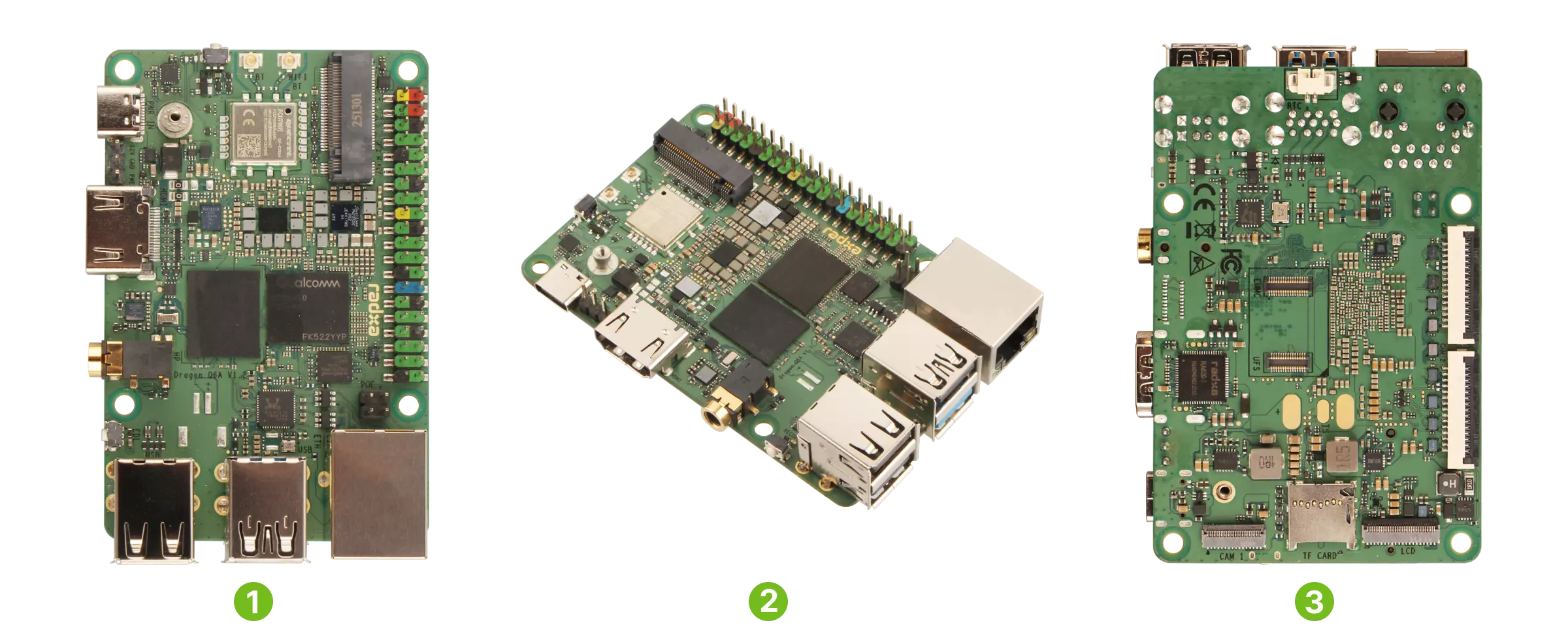
| No. | View | No. | View | No. | View |
|---|---|---|---|---|---|
| ① | Dragon Q6A Front View | ② | Dragon Q6A Side View | ③ | Dragon Q6A Rear View |
Prerequisites
You need to prepare the following hardware in advance:
- Motherboard: Radxa Dragon Q6A
- Host: x86 architecture Windows or Linux
- Display device: HDMI cable and monitor
- System boot media: Radxa eMMC or UFS module
- Power adapter: 12V Type-C power adapter (compatible with PD protocol)
- Radxa PD 30W Power Adapter (Recommended)
- Standard 12V Type-C power adapter, recommended current 2A or above
Software Preparation
We need to download the system image, BIOS firmware, and Qualcomm tools in advance.
Currently, the Dragon Q6A's Android system image only supports flashing using the official Qualcomm tools.
Download Files
The system image and BIOS firmware are in the same compressed package, which can be downloaded from the Resource Summary Download page.
Qualcomm Tools
We need to download and install the Qualcomm Software Center software. After installation, open the Qualcomm Software Center software. If you don't have a Qualcomm account, you can register an account and log in.
In Qualcomm Software Center, search for and install the following tools under Catalog -> Tools:
- Qualcomm USB Driver
- Qualcomm Unifiled Tools Services
- Qualcomm® Chipset Core Tools Stack -> Qualcomm Product Configuration Assistant Tool
Hardware Connection
Install the Radxa eMMC or UFS module onto the Dragon Q6A.
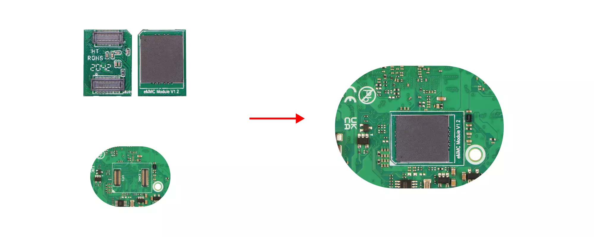
- eMMC Module
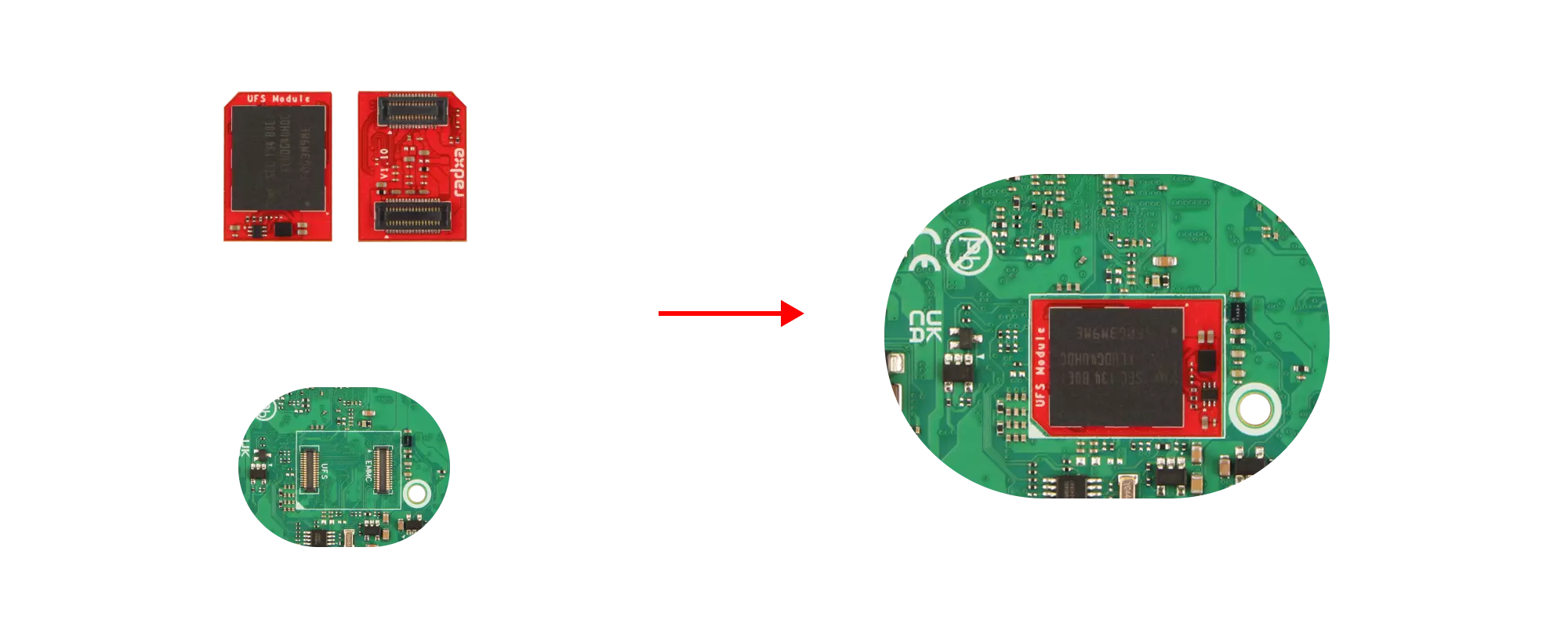
- UFS Module
eMMC module installation steps:
-
Observe the notch direction on the eMMC module and the notch silkscreen on the motherboard's eMMC module interface to determine the correct installation direction.
-
Place the eMMC module above the motherboard's eMMC module interface, ensuring that the eMMC module interface is roughly aligned with the motherboard's eMMC module interface.
-
Press down firmly on one end of the eMMC module. A "click" sound indicates successful installation. Then press the other end in the same way to ensure the eMMC module is installed successfully.
UFS module installation steps:
-
Observe the notch direction on the UFS module and the notch silkscreen on the motherboard's UFS module interface to determine the correct installation direction.
-
Place the UFS module above the motherboard's UFS module interface, ensuring that the UFS module interface is roughly aligned with the motherboard's UFS module interface.
-
Press down firmly on one end of the UFS module. A "click" sound indicates successful installation. Then press the other end in the same way to ensure the UFS module is installed successfully.
Flash System
Flashing the system requires the motherboard to first enter EDL mode.
Enter EDL Mode
Before powering on the motherboard, hold down the EDL button; after powering on the motherboard, release the EDL button to enter EDL mode.
Specific steps:
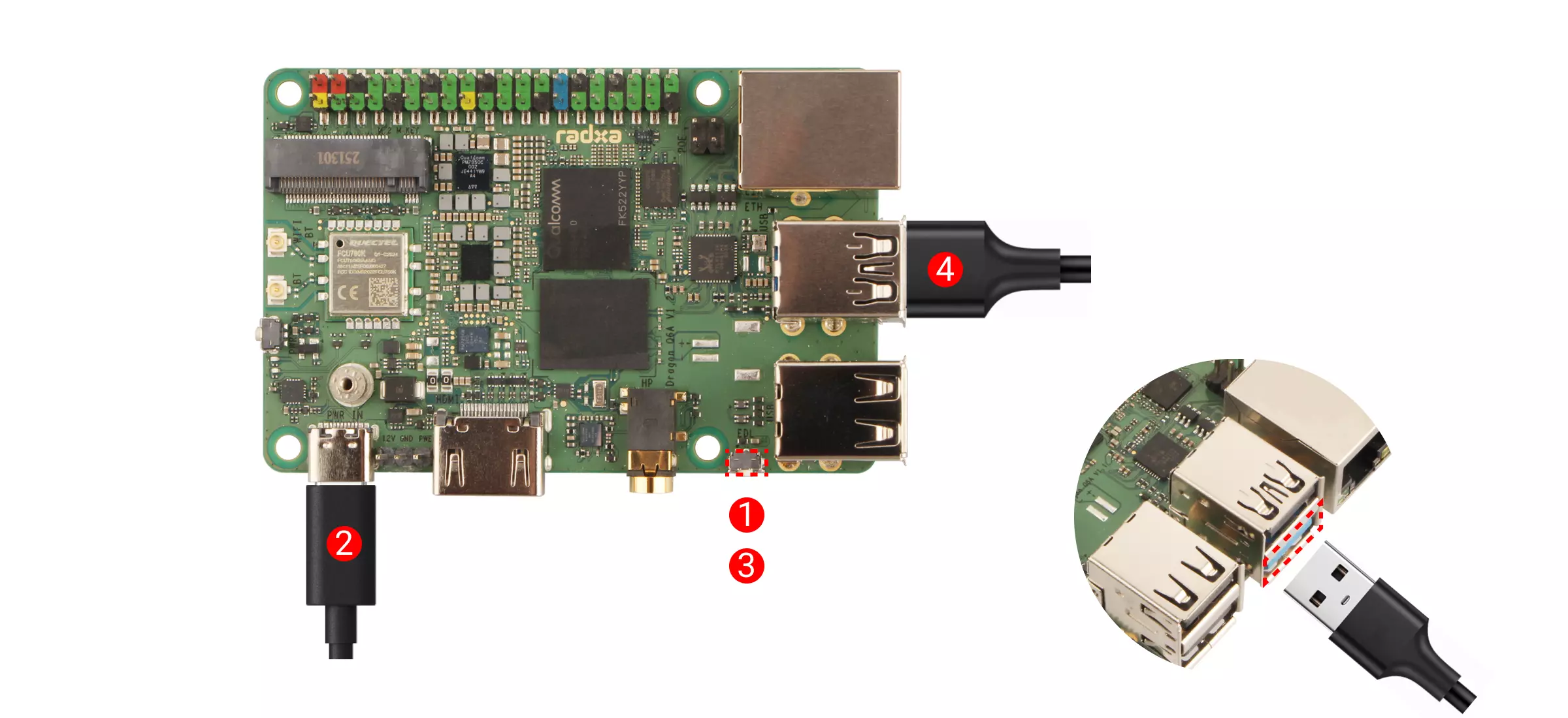
①: Hold down the EDL button
②: Connect a 12V Type-C power adapter (compatible with PD protocol)
③: Release the EDL button
④: Use a dual-head USB Type-A data cable to connect the USB 3.1 Type-A port of the Dragon Q6A to a USB Type-A port on the computer
Connect EDL Device
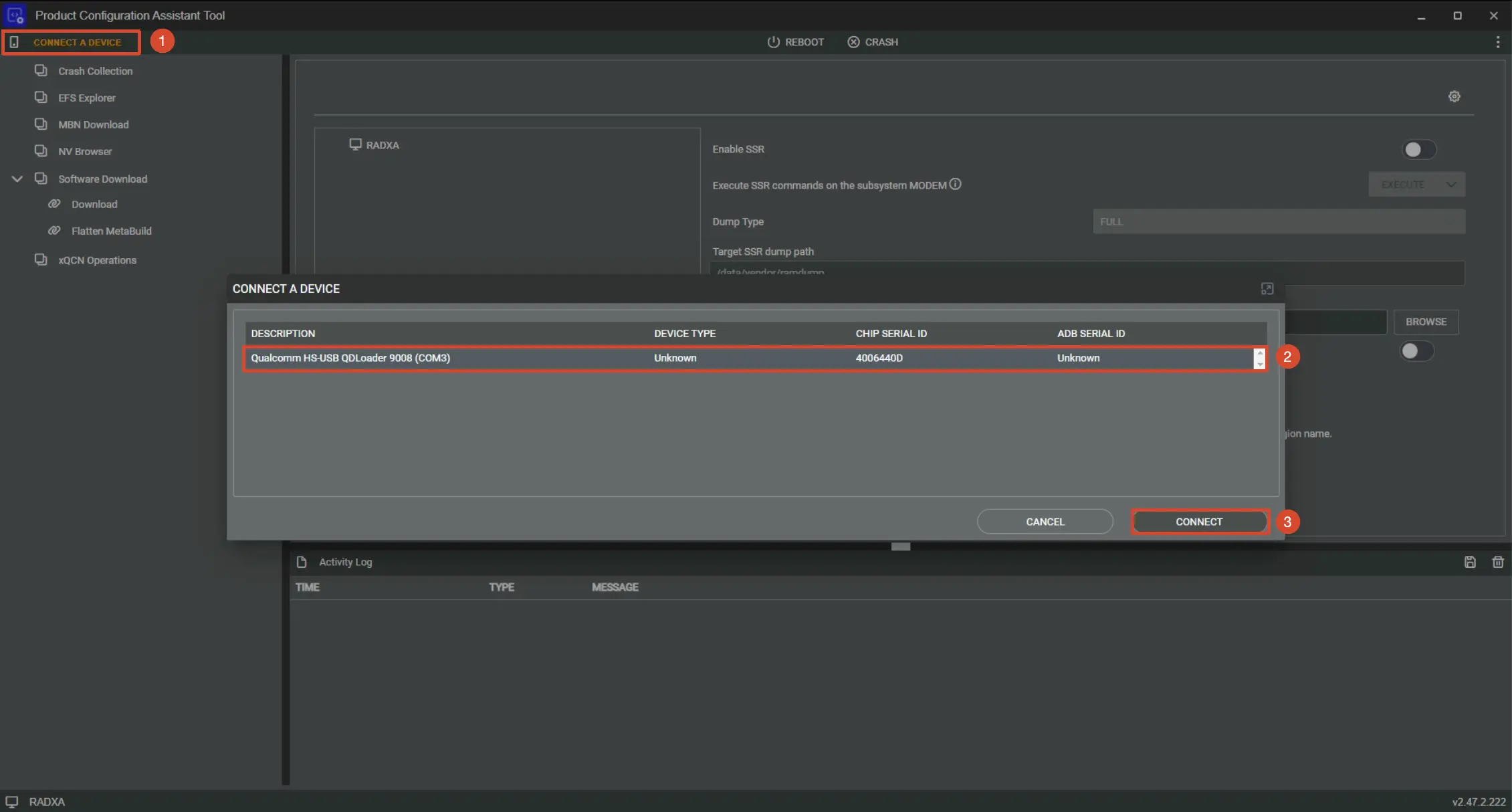
Open the xPCATApp application (after completing the Qualcomm official tools steps, the xPCATApp application will appear in the system's software application list), and connect the corresponding EDL device of the motherboard. Detailed steps are as follows:
①: Click the CONNECT A DEVICE option to select a device
②: Select the corresponding device of the motherboard
③: Click the CONNECT option to connect
Flash BIOS Firmware
The motherboard requires flashing the corresponding BIOS firmware to boot the Android system image. The system image and BIOS firmware are compressed in the same file. The spinor folder extracted from the system image compressed package is the BIOS firmware folder.
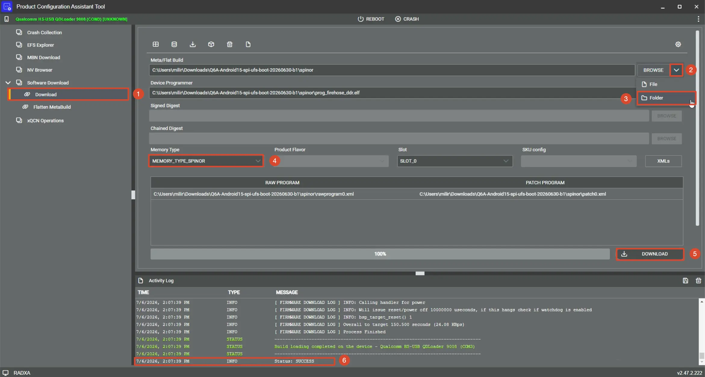
Detailed steps are as follows:
①: Select the Download option
②: Select the file type
③: Select the spinor folder extracted from the system image file
④: For Memory Type, select the MEMORY_TYPE_SPINOR option
⑤: Click the DOWNLOAD option to download
⑥: After a successful download, a SUCCESS prompt will be displayed
Flash System Image
Compared to eMMC, flashing the system to UFS requires an additional step to download the UFS configuration file, which is not required for eMMC.
Download UFS Configuration File
This step is only required when flashing the system to the UFS module. Skip this step when flashing the system to the eMMC module.
Detailed steps are as follows:
①: Select the UFS PROVISIONING option
②: Select the provision_ufs31.xml file
③: Click OK and the UFS configuration will be completed automatically
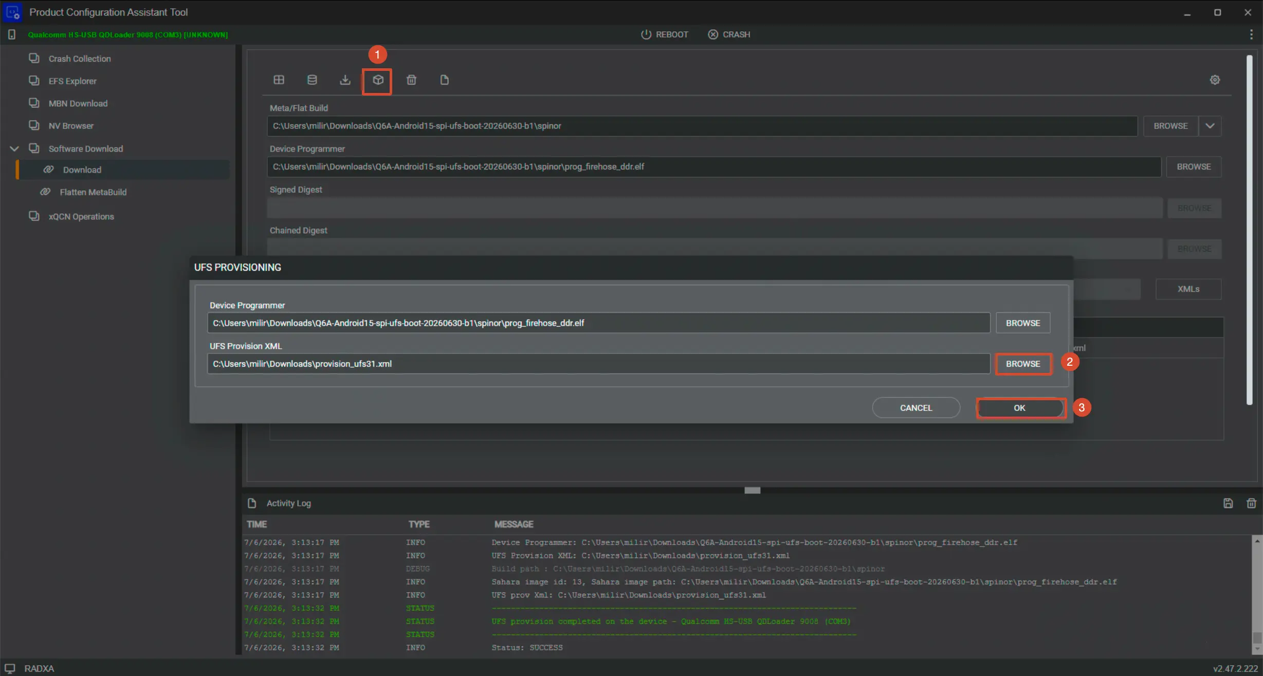
When selecting the provision_ufs31.xml file, you also need to confirm that the Device Programmer option has automatically loaded the prog_firehose_ddr.elf file. If not, manually select the file.
Flash System Image
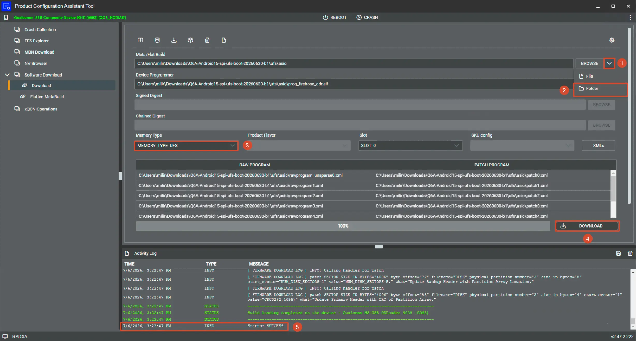
The difference between flashing the eMMC system to the eMMC module and flashing the UFS system to the UFS module mainly lies in the selected system image file and storage type.
Detailed steps are as follows: The diagram uses UFS system flashing as an example
①: Select the file type
②: Select the asic folder extracted from the system image file -> eMMC corresponds to <path>\emmc\asic, UFS corresponds to <path>\ufs\asic
③: The Memory Type option is selected according to the corresponding storage module -> eMMC corresponds to MEMORY_TYPE_EMMC, UFS corresponds to MEMORY_TYPE_UFS
④: Click the DOWNLOAD option to flash the image
⑤: After a successful download, a SUCCESS prompt will be displayed