40-Pin GPIO Interface
The Radxa Dragon Q8B features an onboard 40-pin GPIO (General-Purpose Input/Output) interface, providing highly flexible interface support for hardware expansion.
Users can connect various sensors, actuators, communication modules, displays, and other embedded peripherals via the 40-pin GPIO interface, enabling rapid prototyping and functional verification in fields such as the Internet of Things (IoT), robotics control, and industrial automation.
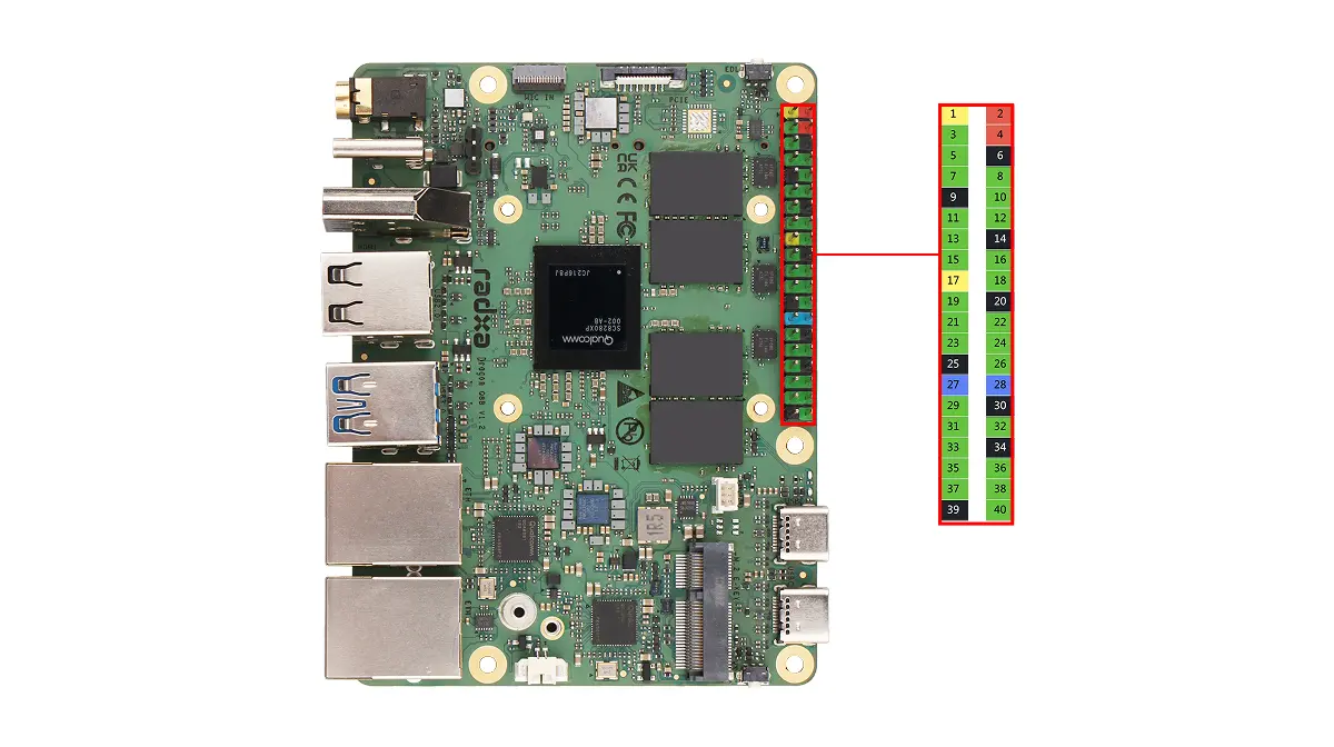
When using the 40-pin GPIO interface, pay attention to the wiring of the pins and peripherals, and ensure that the pins are connected correctly. Improper operation may result in damage to the device hardware.
GPIO Functions
Dragon Q8B supports connecting external devices to the onboard GPIO pins and provides multiple multiplexed functions, including UART, SPI, and I2C.
| Function4 | Function3 | Function2 | Function1 | Function0 | Pin# | Pin# | Function0 | Function1 | Function2 | Function3 |
|---|---|---|---|---|---|---|---|---|---|---|
| 3V3 | 1 | 2 | 5V | |||||||
| SPI9_MISO | UART9_CTS | I2C9_SDA | GPIO_41 | 3 | 4 | 5V | ||||
| SPI9_MOSI | UART9_RFR | I2C9_SCL | GPIO_42 | 5 | 6 | GND | ||||
| SPI4_CS_3 | GPIO_175 | 7 | 8 | GPIO_63 | UART17_TX | |||||
| GND | 9 | 10 | GPIO_64 | UART17_RX | ||||||
| SPI4_CS_1 | I2C5_SDA | GPIO_111 | 11 | 12 | GPIO_174 | UART4_RX | SPI4_CS_0 | |||
| HS-UART18_CTS | SPI18_MISO | UART18_CTS | I2C18_SDA | GPIO_66 | 13 | 14 | GND | |||
| HS-UART18_RFR | SPI18_MOSI | UART18_RFR | I2C18_SCL | GPIO_67 | 15 | 16 | GPIO_68 | UART18_TX | SPI18_SCKL | HS-UART18_TX |
| 3.3V | 17 | 18 | GPIO_110 | |||||||
| SPI20_MOSI | UART20_RFR | I2C20_SCL | GPIO_88 | 19 | 20 | GND | ||||
| SPI20_MISO | UART20_CTS | I2C20_SDA | GPIO_87 | 21 | 22 | GPIO_92 | SPI20_CS_2 | |||
| SPI20_SCKL | UART20_TX | GPIO_89 | 23 | 24 | GPIO_90 | UART20_RX | SPI20_CS_0 | |||
| GND | 25 | 26 | GPIO_91 | SPI20_CS_1 | ||||||
| SPI9_SCKL | UART9_TX | I2C8_SDA | GPIO_43 | 27 | 28 | GPIO_44 | I2C8_SCL | UART9_RX | SPI9_CS_0 | |
| SPI6_CS_0 | UART6_RX | GPIO_157 | 29 | 30 | GND | |||||
| SPI6_SCKL | UART6_TX | GPIO_156 | 31 | 32 | GPIO_114 | CCI_I2C_SCL0 | GCC_GP2_CLK_MIRA | |||
| GCC_GP3_CLK_MRIA | CCI_I2C_SDA1 | GPIO_115 | 33 | 34 | GND | |||||
| SPI4_MISO | UART4_CTS | I2C4_SDA | GPIO_171 | 35 | 36 | GPIO_112 | I2C5_SCL | SPI4_CS_2 | ||
| HS-UART18_RX | SPI18_CS_0 | UART18_RX | GPIO_69 | 37 | 38 | GPIO_172 | I2C4_SCL | UART4_RFR | SPI4_MOSI | |
| GND | 39 | 40 | GPIO_173 | UART4_TX | SPI4_SCKL |
GPIO Usage
This section demonstrates common GPIO usage through the onboard 40-pin GPIO interface.
Install Python Library
Use the python-periphery library to control GPIO pins.
sudo apt update
sudo apt install -y python3-periphery
GPIO Output/Input
Hardware Requirements
- Board
- Dupont wire
Software Requirements
- python-periphery library
Test Code
The following code uses the python-periphery library to control the GPIO_42 pin for outputting high/low levels and reads the GPIO_42 pin's state through the GPIO_175 pin.
gpio_output_input.py
from periphery import GPIO
import time

def gpio_output_with_feedback():
    # GPIO Configuration (modify pin numbers based on your hardware)
    # GPIO_42 (output)  → maps to line 42 of /dev/gpiochip4
    # GPIO_175 (input)  → maps to line 175 of /dev/gpiochip4
    OUTPUT_PIN_CHIP = "/dev/gpiochip4"
    OUTPUT_PIN_NUMBER = 42    # GPIO_42 (output pin, controlled by the script)
    INPUT_PIN_NUMBER = 175    # GPIO_175 (input pin, reads GPIO_42's output state)

    # Initialize GPIO objects as None first (for safe release later)
    gpio_out = None
    gpio_in = None

    try:
        # Initialize GPIO_42 as OUTPUT mode
        gpio_out = GPIO(OUTPUT_PIN_CHIP, OUTPUT_PIN_NUMBER, "out")
        # Initialize GPIO_175 as INPUT mode
        gpio_in = GPIO(OUTPUT_PIN_CHIP, INPUT_PIN_NUMBER, "in")

        # Print test initialization info
        print("=== GPIO Output-Input Feedback Test Started ===")
        print(f"Controlled Pin (GPIO_42): {OUTPUT_PIN_CHIP} - Line {OUTPUT_PIN_NUMBER} (OUTPUT)")
        print(f"Monitoring Pin (GPIO_175): {OUTPUT_PIN_CHIP} - Line {INPUT_PIN_NUMBER} (INPUT)")
        print("Test Behavior: GPIO_42 toggles HIGH/LOW every 1s; GPIO_175 verifies GPIO_42's state")
        print("Press Ctrl+C to stop the test\n")

        # Main loop: Toggle GPIO_42 and read GPIO_175 feedback
        while True:
            # 1. Set GPIO_42 to HIGH level
            gpio_out.write(True)
            time.sleep(0.1)  # Short delay for signal stabilization (avoid read lag)
            gpio175_reading = gpio_in.read()
            print(f"GPIO_42 Output: HIGH (True) | GPIO_175 Reading: {gpio175_reading}")

            # Keep GPIO_42 HIGH for 1 second
            time.sleep(1)

            # 2. Set GPIO_42 to LOW level
            gpio_out.write(False)
            time.sleep(0.1)  # Short delay for signal stabilization
            gpio175_reading = gpio_in.read()
            print(f"GPIO_42 Output: LOW (False) | GPIO_175 Reading: {gpio175_reading}")

            # Keep GPIO_42 LOW for 1 second
            time.sleep(1)

    # Handle user-initiated exit (Ctrl+C)
    except KeyboardInterrupt:
        print("\n\nTest stopped by user (Ctrl+C)")
    # Handle other unexpected errors (e.g., GPIO access failure)
    except Exception as e:
        print(f"\nError during test: {str(e)}")
    # Ensure GPIO resources are released even if an error occurs
    finally:
        print("\nReleasing GPIO resources...")
        # Safely close GPIO_42 (set to LOW first to avoid residual high level)
        if gpio_out:
            try:
                gpio_out.write(False)
                gpio_out.close()
                print(f"Successfully closed GPIO_42 (Line {OUTPUT_PIN_NUMBER})")
            except Exception as close_err:
                print(f"Failed to close GPIO_42 (Line {OUTPUT_PIN_NUMBER}): {str(close_err)}")
        # Safely close GPIO_175
        if gpio_in:
            try:
                gpio_in.close()
                print(f"Successfully closed GPIO_175 (Line {INPUT_PIN_NUMBER})")
            except Exception as close_err:
                print(f"Failed to close GPIO_175 (Line {INPUT_PIN_NUMBER}): {str(close_err)}")
        print("Resource release complete.")

# Run the test when the script is executed directly
if __name__ == "__main__":
    gpio_output_with_feedback()
Test Steps
-
Short-circuit the GPIO_42 and GPIO_175 pins using a Dupont wire (these are pins 5 and 7 of the 40-pin header, respectively)
-
Save the code as
gpio_output_input.py -
Run the test code using the command:
sudo python3 gpio_output_input.py
Expected Results
The terminal will display the output level of GPIO_42 and the level read by GPIO_175.
- False represents a LOW level
- True represents a HIGH level