Interface Usage
Interface Overview
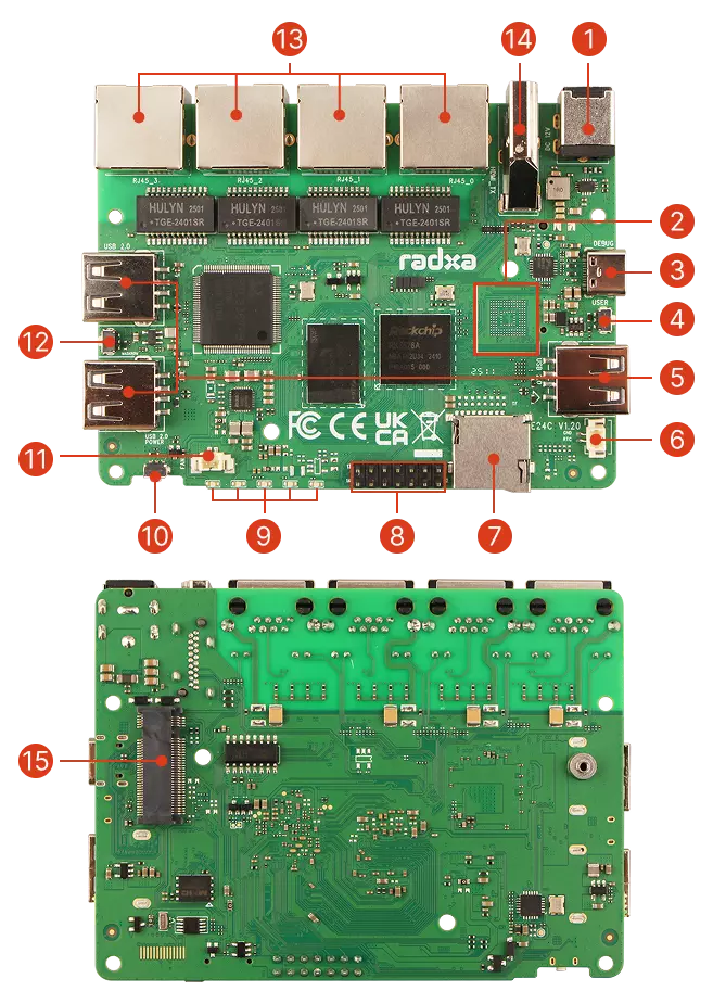
- E24C (Bare Board)
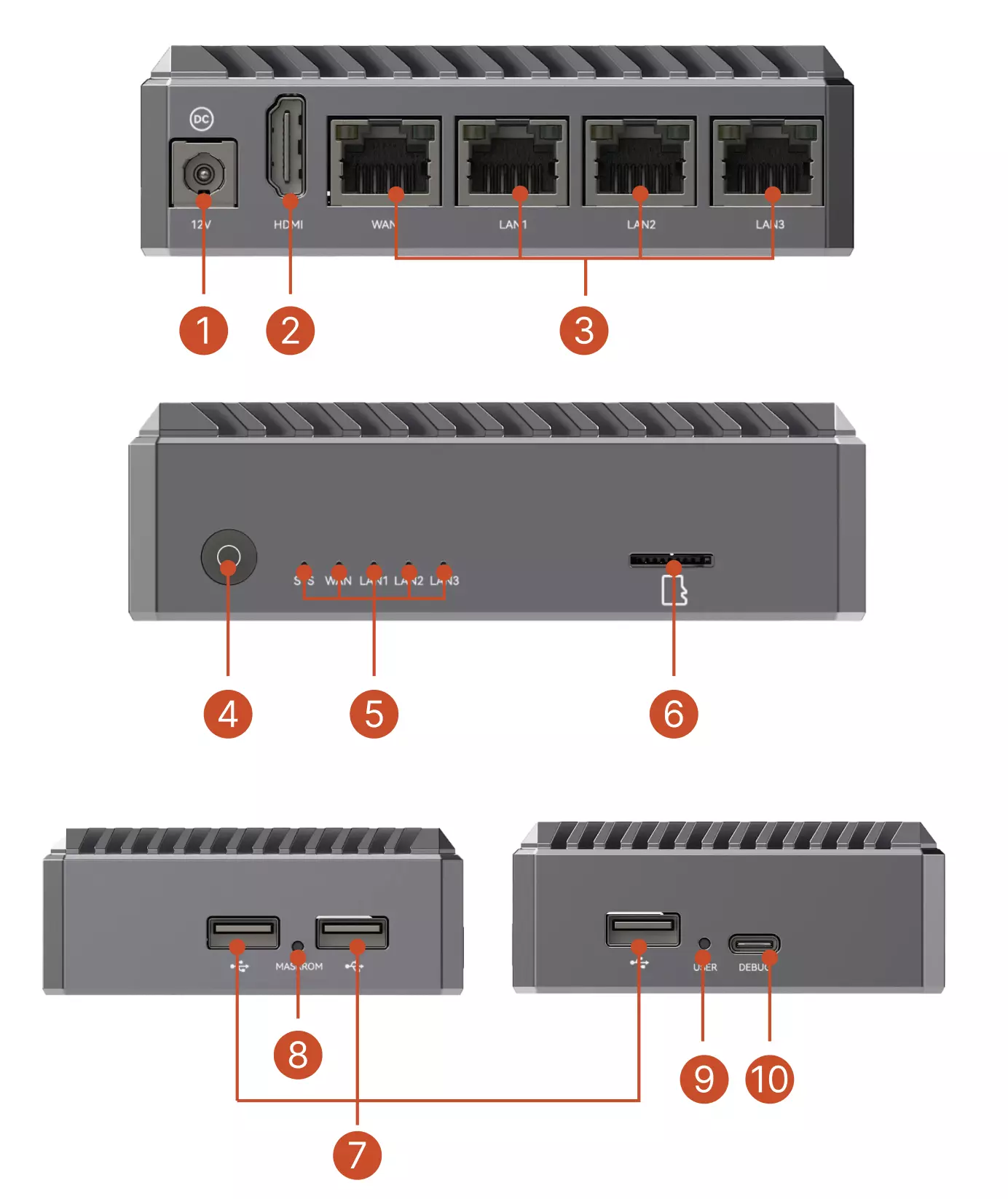
- E24C (Enclosed Version)
| No. | Description | Qty |
|---|---|---|
| ① | Power Interface: DC5525 | 1 |
| ② | Onboard eMMC (optional; mutually exclusive with SPI Nor Flash for boot) | 1 |
| ③ | USB 2.0 Type-C: Combined Device & Debug Port | 1 |
| ④ | User Button | 1 |
| ⑤ | USB 2.0 Type-A Ports | 3 |
| ⑥ | RTC Battery Connector | 1 |
| ⑦ | microSD Card Slot | 1 |
| ⑧ | GPIO: 14-Pin Expansion Header | 1 |
| ⑨ | LED Indicators (1 Power, 4 Ethernet Port LEDs) | 5 |
| ⑩ | Power Button | 1 |
| ⑪ | Fan Header | 1 |
| ⑫ | Maskrom Button | 1 |
| ⑬ | Gigabit Ethernet Ports (Configurable WAN/LAN) | 4 |
| ⑭ | HDMI 2.1 Output | 1 |
| ⑮ | M.2 NVMe SSD Slot | 1 |
| ⑯ | SPI Nor Flash (boot device on some models; mutually exclusive with eMMC) | 1 |
| No. | Description | Qty |
|---|---|---|
| ① | Power Interface: DC5525 | 1 |
| ② | HDMI 2.1 Output | 1 |
| ③ | Gigabit Ethernet Ports (Configurable WAN/LAN) | 4 |
| ④ | Power Button | 1 |
| ⑤ | LED Indicators (1 Power, 4 Ethernet Port LEDs) | 5 |
| ⑥ | microSD Card Slot | 1 |
| ⑦ | USB 2.0 Type-A Ports | 3 |
| ⑧ | Maskrom Button | 1 |
| ⑨ | User Button | 1 |
| ⑩ | USB 2.0 Type-C: Combined Device & Debug Port | 1 |
Interface Description
This section describes the interfaces using the Radxa E24C bare board as an example.
Power Interface
Powered by a 12V/2A power adapter with a DC5525 connector.
Recommended power supplies:
- Radxa DC12 36W Power Adapter (Recommended)
- Radxa DC12 60W Power Adapter
- Standard 12V/2A DC Power Adapter (DC5525 connector)
Onboard eMMC
Optional onboard eMMC storage configuration. Note: Some models use SPI Nor Flash for boot; this is mutually exclusive with onboard eMMC.
USB 2.0 Type-C Port
Serves as a debug port for viewing logs and accessing the device, with a default baud rate of 1500000.
As a data transfer interface, it supports USB 2.0 OTG data transfer and serial debugging.
- USB 2.0 OTG
Supports ADB, USB network, and mass storage.
Example for USB mass storage (ensure SSD is connected via M.2 M-Key before executing commands):
modprobe libcomposite
modprobe usb_f_mass_storage
systemctl daemon-reload
umount /sys/kernel/config
mount -t configfs none /sys/kernel/config
cd /sys/kernel/config/usb_gadget
mkdir -p my_udisk
cd my_udisk
echo 0x1d6b > idVendor
echo 0x0104 > idProduct
echo 0x0100 > bcdDevice
echo 0x0300 > bcdUSB
mkdir -p strings/0x409
echo "123456789" > strings/0x409/serialnumber
echo "My Manufacturer" > strings/0x409/manufacturer
echo "My USB Disk" > strings/0x409/product
mkdir -p configs/c.1
mkdir -p configs/c.1/strings/0x409
echo "Mass Storage Config" > configs/c.1/strings/0x409/configuration
mkdir -p functions/mass_storage.usb0
mkfs.ext4 /dev/nvme0n1p1
echo /dev/nvme0n1p1 > functions/mass_storage.usb0/lun.0/file
ln -s functions/mass_storage.usb0 configs/c.1
echo fc000000.usb > UDC
User Button
Programmable button with software-configurable functionality.
USB 2.0 Type-A Ports
Three USB 2.0 ports for connecting external devices such as keyboards, mice, and storage devices.
RTC Battery Connector
2-Pin 1.25mm RTC battery connector for connecting a real-time clock battery to maintain accurate system time during power loss.
microSD Card Slot
For inserting a microSD card, which can be used as a system boot device or for additional storage.
GPIO: 14-Pin Expansion Header
14-Pin 0.1" (2.54mm) interface supporting multiple functions including SPI, UART, I2C, and power output.
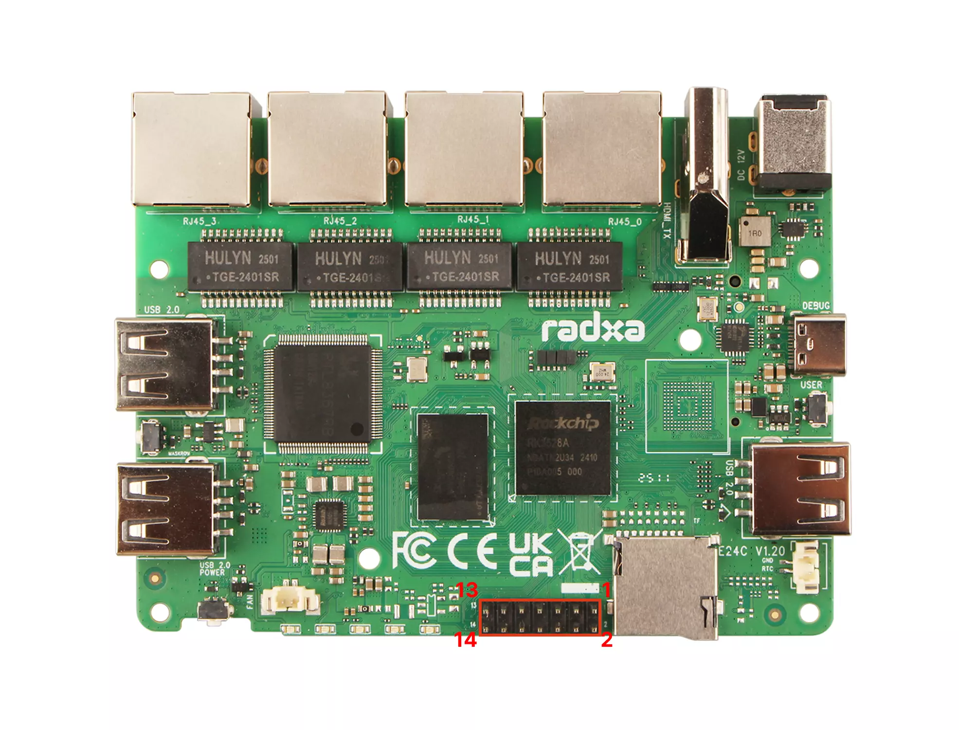
GPIO Pin Definition Table
| Pin# | Function 1 | Function 2 |
|---|---|---|
| 1 | VCC_3V3 | |
| 2 | VCC5V0_SYS | |
| 3 | GPIO1_B3 | I2C5_SDA_M0 |
| 4 | GND | |
| 5 | GPIO1_B2 | I2C5_SCL_M0 |
| 6 | GPIO4_A4 | |
| 7 | GPIO1_B7 | SPI1_MOSI |
| 8 | GPIO4_A5 | |
| 9 | GPIO1_C0 | SPI1_MISO |
| 10 | GPIO4_A6 | UART1_TX_M0 |
| 11 | GPIO1_B6 | SPI1_CLK |
| 12 | GPIO4_B4 | |
| 13 | GPIO1_C1 | SPI1_CSN0 |
| 14 | GPIO4_A7 | UART1_RX_M0 |
All signal pins are 3.3V level. Do not connect 5V signals as this may damage the single-board computer.
GPIO Usage Example
# Install GPIO control tools
sudo apt-get install gpiod
# List available GPIO chips
gpiodetect
# View GPIO status
gpioinfo
# Control GPIO output
gpioset <chip> <line>=<value>
# Read GPIO input
gpioget <chip> <line>
Common Peripheral Connection Examples
I2C Sensor Connection
# Install I2C tools
sudo apt-get install i2c-tools
# Scan for I2C devices
sudo i2cdetect -y 2 # Assuming I2C2 is used
# Read I2C device register
sudo i2cget -y 2 0x48 0x00 # Read register 0x00 from device at address 0x48
# Write to I2C device register
sudo i2cset -y 2 0x48 0x01 0x55 # Write 0x55 to register 0x01 of device at address 0x48
LED Status Indicators
Five status indicators showing power and network status. Refer to the silkscreen on the Radxa E24C bare board to identify each indicator.
- Power LED: Green light when power is connected
- Network Status LEDs: Blink in sync with corresponding network port activity
Power Button
Used to power the device on and off.
Fan Header
2-Pin 1.25mm fan header for connecting a cooling fan.
Maskrom Button
Used to enter Maskrom mode for firmware flashing.
Gigabit Ethernet Ports
Four Gigabit Ethernet ports.
In OpenWrt systems, these interfaces can be flexibly configured as WAN (Wide Area Network) or LAN (Local Area Network) ports, providing a highly customizable networking solution. Multiple ports also offer redundancy and load balancing capabilities, enhancing network reliability and performance.
- Unique MAC Address
The Radxa E24C has a unique and fixed MAC address that remains consistent across power cycles, reboots, and even after reflashing the firmware.
- Network Speed Test
# Install iperf3 tool
sudo apt install iperf3
# Run on the server side
iperf -s
# Test upload speed
iperf3 -c server-ip -t 60
# Test download speed
iperf3 -c server-ip -t 60 -R
HDMI 2.1 Output Port
Supports video output up to 4K resolution, compatible with monitors and TVs.
M.2 NVMe SSD Interface
Provides a PCIe 2.1 1-lane interface for connecting M.2 NVMe SSDs. Supports standard M.2 2280 form factor NVMe SSDs. Note: M.2 SATA SSDs are not supported.