Hardware Interfaces and Design
Hardware Overview
The Radxa E24C is a compact, high-performance network computer powered by the Rockchip RK3528A processor, designed for routing, edge networking, and industrial applications. It achieves an optimal balance between performance, connectivity, and reliability.
This document details the hardware interfaces, connection methods, and application recommendations for the E24C to help you maximize the device's performance.
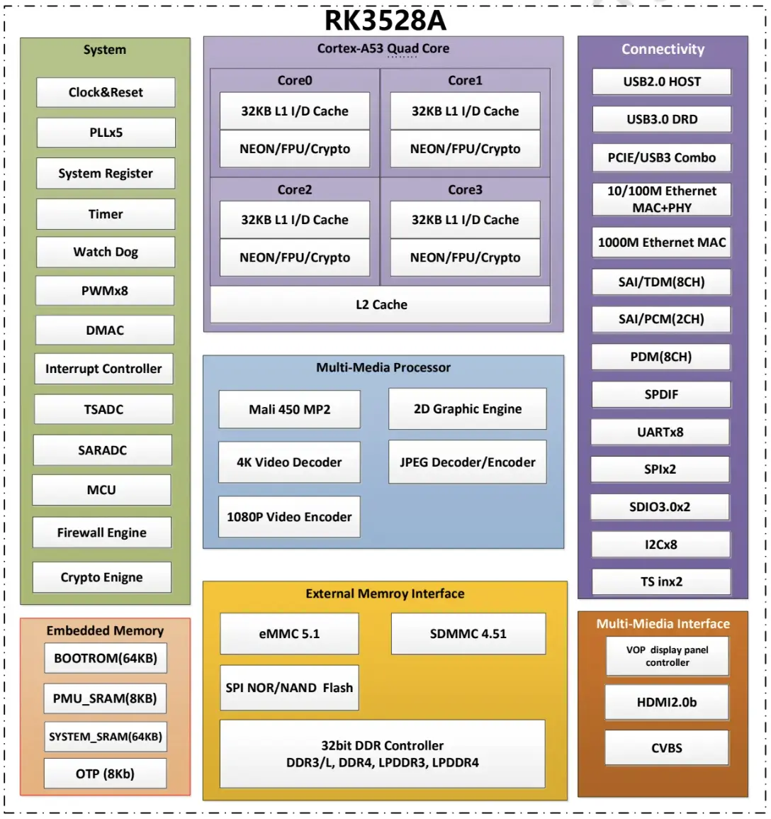
Chip Architecture
The RK3528A is a high-performance processor from Rockchip, featuring high performance, low power consumption, and cost-effectiveness.
- Powerful Processing: Quad-core ARM Cortex-A53
- Networking Capabilities: Supports multiple Gigabit network interfaces, optimized for networking applications
- Diverse Interfaces: Supports various high-speed interfaces including PCIe, USB 3.0, and HDMI 2.1
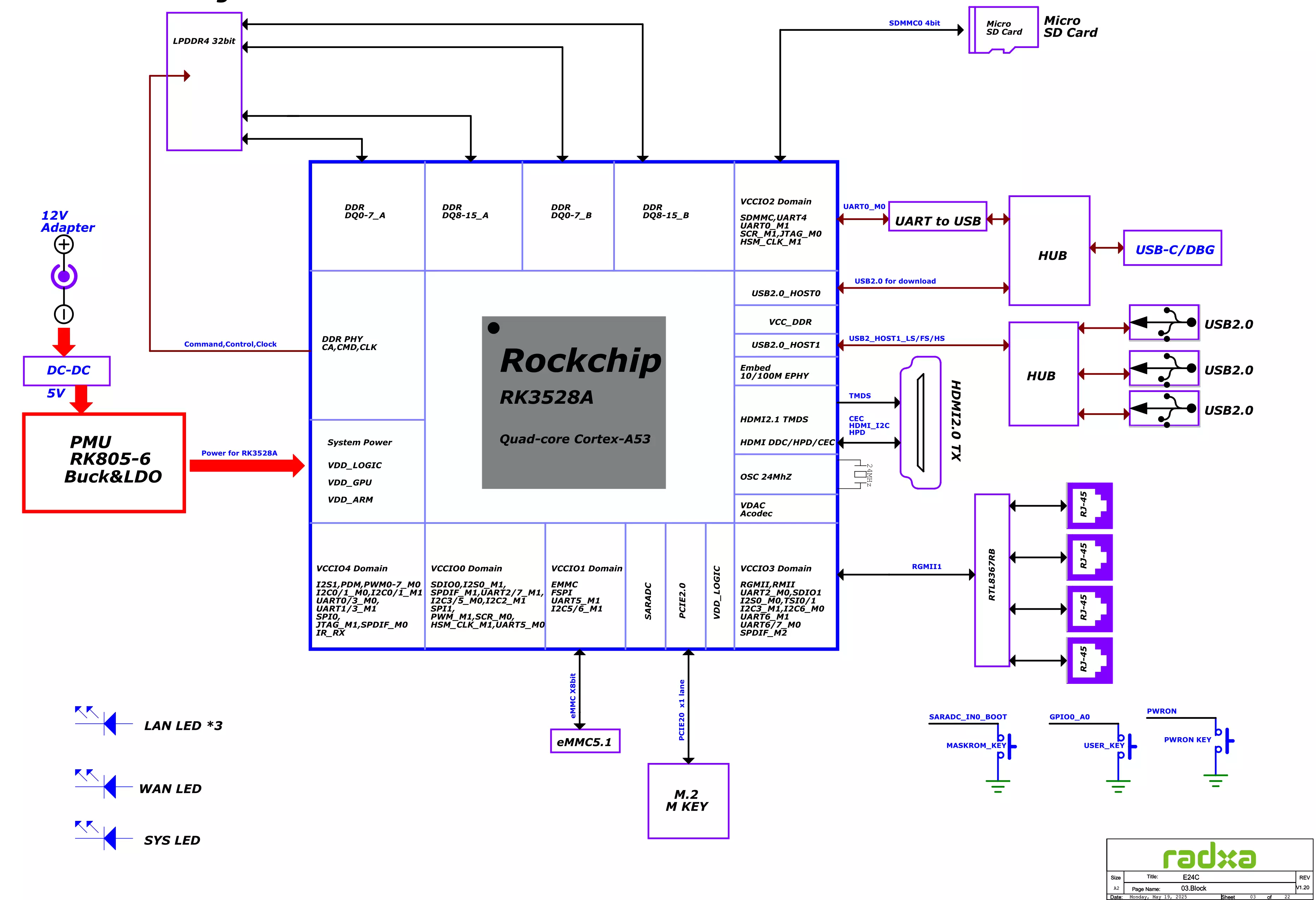
System Architecture
The E24C adopts a compact and efficient hardware design, integrating multiple interfaces and functions on a single board.
Hardware Interfaces
For detailed hardware interface pinouts of Radxa E24C, refer to the Hardware Schematic
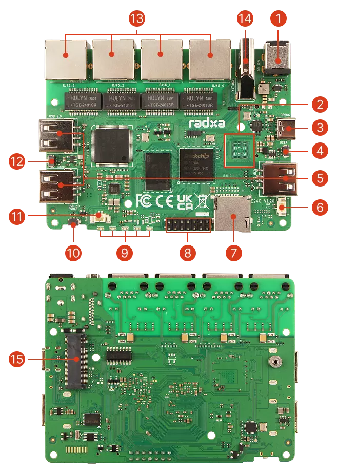
| No. | Description | Qty |
|---|---|---|
| 1 | Power Input: DC5525 | 1 |
| 2 | Onboard eMMC | 1 |
| 3 | USB 2.0 Type-C (OTG + UART Debug) | 1 |
| 4 | User Button | 1 |
| 5 | USB 2.0 Type-A Ports | 3 |
| 6 | RTC Battery Connector | 1 |
| 7 | microSD Card Slot | 1 |
| 8 | GPIO: 14-pin Expansion Header | 1 |
| 9 | LED Indicators (1x Power, 4x Ethernet) | 5 |
| 10 | Power Button | 1 |
| 11 | Fan Header | 1 |
| 12 | Maskrom Button | 1 |
| 13 | Gigabit Ethernet Ports | 4 |
| 14 | HDMI 2.1 Output | 1 |
| 15 | M.2 NVMe SSD Slot | 1 |
| 16 | SPI Nor Flash | 1 |
microSD Card Slot
The E24C features a microSD card slot, which can be used for storing system data, system images, and system configurations.
| PIN | Name | Function Description |
|---|---|---|
| 1 | SDMMC_D2 | SD card data line 2 |
| 2 | SDMMC_D3 | SD card data line 3 |
| 3 | SDMMC_CMD | SD card command line |
| 4 | VCC_3V3 | 3.3V power supply |
| 5 | SDMMC_CLK | SD card clock signal |
| 6 | GND | Ground |
| 7 | SDMMC_D0 | SD card data line 0 |
| 8 | SDMMC_D1 | SD card data line 1 |
| 9 | SDMMC_DETN | SD card insertion detection |
| 10 | GND | Ground |
| 11 | GND | Ground |
| 12 | GND | Ground |
| 13 | GND | Ground |
Usage Guide
- Supported Card Types: Compatible with microSD/microSDHC/microSDXC memory cards
- Recommended Specifications: Class 10/UHS-I or higher recommended for better performance
- Maximum Capacity: Theoretically supports up to 2TB microSDXC cards, tested with 512GB cards
Main Application Scenarios
- System Boot: E24C can boot the operating system from a microSD card, which is the most common usage
- Data Storage: Can be used to expand storage space when the system is already running (e.g., when booted from eMMC)
- System Backup: Can be used to back up the current system and data
For production environments or systems requiring 24/7 operation, it is recommended to use eMMC or M.2 SSD as the primary storage and boot device, as they provide better stability and read/write endurance. microSD cards are suitable for temporary storage and development/testing scenarios.
USB Interfaces
E24C provides two different types of USB interfaces: USB 2.0 Type-C and USB 2.0 Type-A.
USB 2.0 Type-C
Serves as a data transfer interface, supporting USB 2.0 OTG data transfer and serial debugging, with data transfer rates up to 480Mbps.
USB 2.0 Type-A
Three USB 2.0 Type-A interfaces, supporting data transfer rates up to 480Mbps.
| PIN | Name | Description |
|---|---|---|
| 1 | VCC5V0_USB | 5V Power Output, max 500mA |
| 2 | USB2_HOST_DM | USB 2.0 Data- |
| 3 | USB2_HOST_DP | USB 2.0 Data+ |
| 4 | GND | Ground |
Usage Recommendations:
- Input devices like mice and keyboards
- Low-bandwidth peripherals (printers, scanners, etc.)
- External devices supporting USB 2.0
HDMI Interface
E24C features a standard HDMI 2.1 interface supporting up to 4K video output, suitable for connecting to external displays, TVs, and other devices.
| PIN | Name | Description |
|---|---|---|
| 1 | HDMI_TX2+ | HDMI High-Speed Data Lane 2+ |
| 2 | GND | Ground |
| 3 | HDMI_TX2- | HDMI High-Speed Data Lane 2- |
| 4 | HDMI_TX1+ | HDMI High-Speed Data Lane 1+ |
| 5 | GND | Ground |
| 6 | HDMI_TX1- | HDMI High-Speed Data Lane 1- |
| 7 | HDMI_TX0+ | HDMI High-Speed Data Lane 0+ |
| 8 | GND | Ground |
| 9 | HDMI_TX0- | HDMI High-Speed Data Lane 0- |
| 10 | HDMI_TXC+ | HDMI Clock+ |
| 11 | GND | Ground |
| 12 | HDMI_TXC- | HDMI Clock- |
| 13 | HDMI_CEC | Consumer Electronics Control for device control |
| 14 | NC | No Connection |
| 15 | HDMI_SCL | DDC Clock for EDID information |
| 16 | HDMI_SDA | DDC Data for EDID information |
| 17 | GND | Ground |
| 18 | VCC5V0_HDMI | 5V Power Output |
| 19 | HDMI_HPD | Hot Plug Detect Signal |
Gigabit Ethernet Interface
The E24C is equipped with 4 Gigabit Ethernet ports, which are the core functional components of the product, supporting various network application scenarios.
| PIN | Name | Description |
|---|---|---|
| 1 | ETH_TXP | Gigabit Ethernet Transmit+ |
| 2 | ETH_TXN | Gigabit Ethernet Transmit- |
| 3 | ETH_RXP | Gigabit Ethernet Receive+ |
| 4 | NC | Not Connected |
| 5 | NC | Not Connected |
| 6 | ETH_RXN | Gigabit Ethernet Receive- |
| 7 | NC | Not Connected |
| 8 | NC | Not Connected |
Gigabit Network Controller
The Gigabit network interface of E24C is driven by the network controller integrated in the Rockchip RK3528A SoC, with main features including:
- Full-Duplex Gigabit Ethernet: Each port supports 10/100/1000 Mbps speeds
- MDI/MDIX Auto-Detection: Automatically identifies straight-through and crossover cables
- IEEE 802.3 Compliance: Supports standard Ethernet protocols
- Hardware Flow Control: Supports IEEE 802.3x flow control
- Internal MAC Addresses: Each port is assigned an independent MAC address
Network Configuration Scenarios
The four Gigabit Ethernet ports allow flexible configuration of various network topologies:
1. Multi-WAN Router Configuration
Multiple ports can be configured as WAN interfaces to achieve:
- Multi-line load balancing
- Link aggregation
- Multi-ISP backup connections
2. Network Switch Configuration
Configure all ports in switch mode for:
- Network segmentation (VLAN)
- QoS priority control
- Port mirroring and monitoring
3. Combined Mode
The most common configuration: 1 WAN + 3 LAN ports:
- 1 port connects to the upstream router/modem
- 3 ports for internal network device connections
Usage Recommendations
- Use CAT 5e or higher specification network cables for full Gigabit performance
- Multi-WAN configuration requires specialized routing software support, such as iStoreOS or OpenWrt
- Pay attention to heat dissipation when running high-traffic network applications
For applications requiring powerful network performance (such as enterprise routing, gateways, etc.), you can configure Port Bonding to increase bandwidth and reliability. These advanced features can be easily configured in iStoreOS or OpenWrt.
M.2 M Key Interface
| PIN | Name |
|---|---|
| 1 | GND |
| 2 | VCC3V3_PCIE |
| 3 | GND |
| 4 | VCC3V3_PCIE |
| 5 | GND |
| 6 | NC |
| 7 | GND |
| 8 | NC |
| 9 | GND |
| 10 | NC |
| 11 | GND |
| 12 | NC |
| 13 | GND |
| 14 | NC |
| 15 | GND |
| 16 | NC |
| 17 | GND |
| 18 | NC |
| 19 | GND |
| 20 | NC |
| 21 | GND |
| 22 | NC |
| 23 | GND |
| 24 | NC |
| 25 | GND |
| 26 | NC |
| 27 | GND |
| 28 | NC |
| 29 | GND |
| 30 | NC |
| 31 | GND |
| 32 | NC |
| 33 | GND |
| 34 | NC |
| 35 | GND |
| 36 | NC |
| 37 | GND |
| 38 | NC |
| 39 | VCC3V3_PCIE |
| 40 | NC |
| 41 | VCC3V3_PCIE |
| 42 | NC |
| 43 | GND |
| 44 | NC |
| 45 | NC |
| 46 | NC |
| 47 | GND |
| 48 | NC |
| 49 | GND |
| 50 | PCIE_CLKREQ_N |
| 51 | GND |
| 52 | PCIE_WAKE_N |
| 53 | GND |
| 54 | PCIE_REFCLK_P |
| 55 | PCIE_REFCLK_N |
| 56 | NC |
| 57 | GND |
| 58 | PCIE_RX_N |
| 59 | PCIE_RX_P |
| 60 | GND |
| 61 | GND |
| 62 | PCIE_TX_N |
| 63 | PCIE_TX_P |
| 64 | GND |
| 65 | GND |
| 66 | NC |
| 67 | NC |
| 68 | PCIE_RST_N |
| 69 | GND |
| 70 | NC |
| 71 | GND |
| 72 | NC |
| 73 | GND |
| 74 | NC |
| 75 | GND |
Fan Interface (2-Pin 1.25mm)
| PIN | Name |
|---|---|
| 1 | PWM |
| 2 | GND |
RTC Battery Interface (2-Pin 1.25mm)
| PIN | Name |
|---|---|
| 1 | VCC3V0_RTC |
| 2 | GND |
14-Pin GPIO Interface (0.1"/2.54mm)
| Pin# | Function 1 | Function 2 |
|---|---|---|
| 1 | VCC_3V3 | |
| 2 | VCC5V0_SYS | |
| 3 | GPIO1_B3 | I2C5_SDA_M0 |
| 4 | GND | |
| 5 | GPIO1_B2 | I2C5_SCL_M0 |
| 6 | GPIO4_A4 | |
| 7 | GPIO1_B7 | SPI1_MOSI |
| 8 | GPIO4_A5 | |
| 9 | GPIO1_C0 | SPI1_MISO |
| 10 | GPIO4_A6 | UART1_TX_M0 |
| 11 | GPIO1_B6 | SPI1_CLK |
| 12 | GPIO4_B4 | |
| 13 | GPIO1_C1 | SPI1_CSN0 |
| 14 | GPIO4_A7 | UART1_RX_M0 |