Interface Usage Guide
Interface Overview
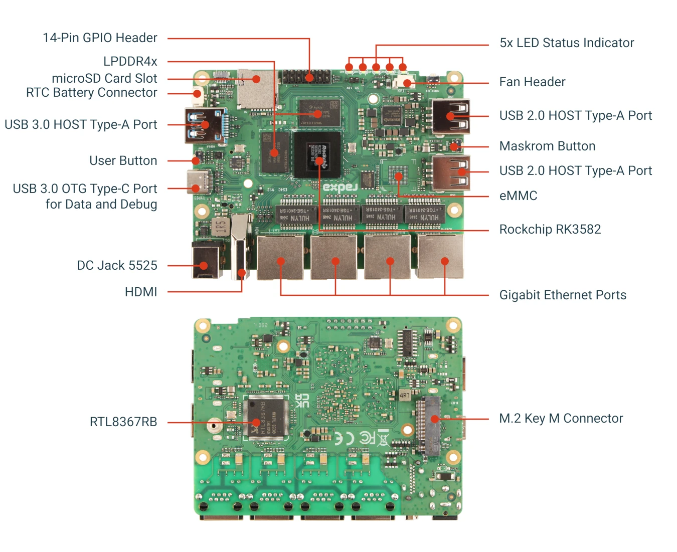
Interface Description
Power Status LED
Power status indicator, lights up green when the device is powered on.
Network Status LEDs
Four network port status indicators that light up according to the signal changes of each network port.
User Button
User-programmable button, functionality can be customized through software.
Power Button
Used to turn the device on and off.
12V DC Power Connector
Power input, Radxa E54C uses 12V voltage input with a standard 5525 DC connector. Please refer to Power Supply Options.
Gigabit Ethernet Ports
Radxa E54C provides four gigabit Ethernet ports. In an OpenWrt system, these interfaces can be flexibly configured as WAN (Wide Area Network interface) or LAN (Local Area Network interface) ports, providing users with highly customizable network solutions. Multiple ports also provide redundancy and load balancing capabilities, enhancing network reliability and performance.
Unique MAC Address
The MAC address of Radxa E54C is unique and fixed. It remains unchanged after each power cycle or software restart, and even after reflashing the system.
Network Speed Testing
- Install the iperf3 tool
sudo apt-get install iperf3
- Run the command on the server side:
iperf -s
- Speed Testing
- Test upload speed
iperf3 -c server-ip -t 60
- Test download speed
iperf3 -c server-ip -t 60 -R
USB Type-C Port
Used as a debug port for viewing logs and accessing the device, with a default baud rate of 1500000.
Also serves as a data transfer interface, supporting USB3.0 OTG, firmware flashing, and DP display output.
USB3.0 OTG
Supports adb.
Supports usbnet.
Supports mass storage.
USB Mass Storage with NVMe SSD
The following example demonstrates setting up USB mass storage using an NVMe SSD. Make sure to connect an SSD to the M-Key slot before executing these commands.
modprobe libcomposite
modprobe usb_f_mass_storage
systemctl daemon-reload
umount /sys/kernel/config
mount -t configfs none /sys/kernel/config
cd /sys/kernel/config/usb_gadget
mkdir -p my_udisk
cd my_udisk
echo 0x1d6b > idVendor
echo 0x0104 > idProduct
echo 0x0100 > bcdDevice
echo 0x0300 > bcdUSB
mkdir -p strings/0x409
echo "123456789" > strings/0x409/serialnumber
echo "My Manufacturer" > strings/0x409/manufacturer
echo "My USB Disk" > strings/0x409/product
mkdir -p configs/c.1
mkdir -p configs/c.1/strings/0x409
echo "Mass Storage Config" > configs/c.1/strings/0x409/configuration
mkdir -p functions/mass_storage.usb0
mkfs.ext4 /dev/nvme0n1p1
echo /dev/nvme0n1p1 > functions/mass_storage.usb0/lun.0/file
ln -s functions/mass_storage.usb0 configs/c.1
echo fc000000.usb > UDC
The above commands configure USB 3.0 mass storage. If you need USB 2.0 mass storage configuration, simply change echo 0x0300 > bcdUSB to echo 0x0200 > bcdUSB.
Connect your PC to the E54C using a USB Type-A to Type-C cable, and the following will appear on your PC:
$ lsblk
NAME        MAJ:MIN RM   SIZE RO TYPE MOUNTPOINTS
...
sdb           8:16   1 953.9G  0 disk /media/devmon/sdb-usb-Linux_File-Stor_
...
You can copy files to this mass storage device:
$ lsblk
NAME        MAJ:MIN RM   SIZE RO TYPE MOUNTPOINTS
...
cp /home/lsj/Downloads/test.wav /media/devmon/sdb-usb-Linux_File-Stor_
md5sum /media/devmon/sdb-usb-Linux_File-Stor_/test.wav
...
View on the E54C:
systemctl daemon-reload
mount /dev/nvme0n1p1 /mnt/
ls /mnt/
md5sum /mnt/test.wav
DP Display
Supports 4K resolution. Note that the display will require separate power supply.
Maskrom Button
Maskrom button is used to enter Maskrom mode for flashing firmware.
HDMI 2.1 Port
Supports video output with resolutions up to 8K, allowing connection to monitors or TVs.
USB 3.0 Type-A Port
Provides a high-speed USB 3.0 interface for connecting external devices such as storage devices, network adapters, etc.
USB 2.0 Type-A Ports
Provides two USB 2.0 interfaces for connecting external devices such as keyboards, mice, storage devices, etc.
Peripheral Connection Testing
Repeatedly connect and disconnect USB peripherals to ensure they are recognized properly each time and function normally.
Storage device recognition:
$ lsusb
  Bus 001 Device 003: ID 067b:2731 Prolific Technology, Inc. USB SD Card Reader
As shown above, a Micro-SD Card Reader has been successfully recognized.
Transfer Rate Testing
- Identify the USB storage device
Use lsblk to confirm the USB storage device
$ lsblk
NAME         MAJ:MIN RM  SIZE RO TYPE MOUNTPOINT
sda            8:0    1 29.3G  0 disk
├─sda1         8:1    1  256M  0 part
└─sda2         8:2    1   29G  0 part
mmcblk0      179:0    0 14.5G  0 disk
├─mmcblk0p1  179:1    0  256M  0 part /boot
└─mmcblk0p2  179:2    0 14.2G  0 part /
- Test read/write speeds
# Test write speed
dd if=/dev/zero of=/mnt/usb/test.img bs=1M count=1024 oflag=direct

# Test read speed
dd if=/mnt/usb/test.img of=/dev/null bs=1M count=1024 iflag=direct
microSD Card Slot
Used for inserting a microSD storage card, which can serve as a system boot drive or additional storage space.
M.2 M-Key Slot
Provides a PCIe 2.1 1-lane interface for connecting M.2 NVMe SSDs. Supports standard M.2 2280 form factor NVMe SSDs. Note that M.2 SATA SSDs are not supported.
Installing an NVMe SSD
- Make sure the device is powered off and disconnected from power
- Insert the M.2 NVMe SSD into the M.2 M-Key slot
- Secure the SSD with the screw
- Connect power and start the device
Testing NVMe SSD Performance
# Install testing tools
sudo apt-get install hdparm

# Test read performance
sudo hdparm -t /dev/nvme0n1

# Use dd to test write performance
sudo dd if=/dev/zero of=/mnt/nvme/test.img bs=1M count=1024 oflag=direct
GPIO Expansion Header
A 14-Pin 0.1" (2.54mm) interface that supports various interface functions:
- 1x SPI
- 1x UART
- 1x I2C
- 2x 5V power outputs
- 1x 3.3V power output
GPIO Usage Example
# Install GPIO control tools
sudo apt-get install gpiod

# List available GPIO chips
gpiodetect

# View GPIO status
gpioinfo

# Control GPIO output
gpioset <chip> <line>=<value>

# Read GPIO input
gpioget <chip> <line>
Fan Connector
2-Pin 1.25mm fan connector for connecting a cooling fan.
RTC Battery Connector
2-Pin 1.25mm RTC battery connector for connecting a real-time clock battery, which keeps the system time accurate even after power is disconnected.