Hardware Interfaces and Design
Hardware Overview
Radxa E54C is a high-performance edge AI network computing device, powered by the Rockchip RK3582 processor, providing powerful performance and diverse interfaces for networking and AI edge computing. This document details the E54C's hardware interfaces, connection methods, and application recommendations to help you fully utilize the device's capabilities.
RK3582 Chip Architecture
Processor Features
RK3582 is a high-performance SoC designed by Rockchip, optimized for edge computing and network applications. Its main features include:
- Powerful Processing Performance: Dual-core Cortex-A76 (2.4GHz) + Quad-core Cortex-A55 (1.8GHz)
- Network Capabilities: Supports multiple gigabit network interfaces, optimized for network applications
- AI Acceleration: Built-in NPU with computing power up to 5TOPs@INT8
- Low Power Design: Suitable for 24x7 operation edge devices
- Diverse Interfaces: Supports PCIe, USB 3.0, HDMI 2.1, and other high-speed interfaces
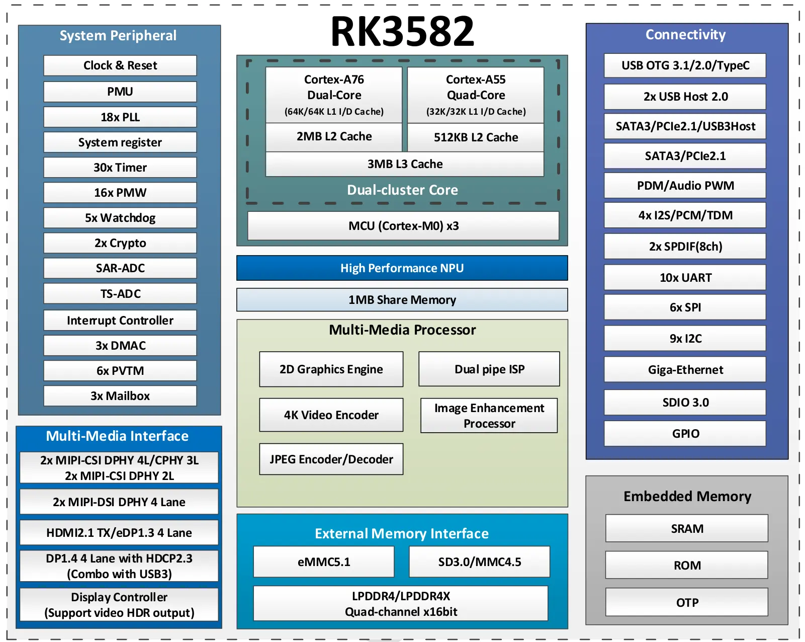
- Network Optimization: Compared to similar chips, RK3582 has been specially optimized for multi-port network applications
- AI Processing: The built-in NPU can efficiently handle AI inference tasks, reducing CPU load
- Expandability: Supports PCIe interface, allowing high-speed storage expansion or other functionality through M.2
System Architecture
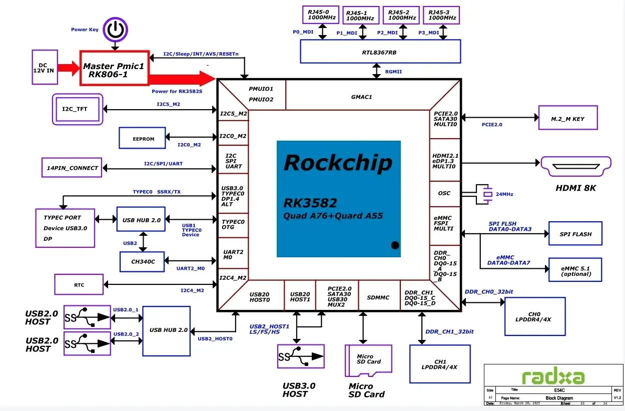
E54C adopts a compact and efficient hardware design, integrating multiple interfaces and functions on a single board. The following diagram shows the system architecture of Radxa E54C, clearly displaying the connection relationships between various components.
System Components and Data Flow
The above diagram shows the data channels and connection methods between the RK3582 SoC and various hardware components:
- Gigabit Network Interface: 4 gigabit Ethernet ports directly connected to the SoC through built-in controllers
- USB Interface: USB 3.0 and USB 2.0 interfaces connected to the main processor through independent buses
- Display Output: HDMI 2.1 interface providing high-resolution output through dedicated controllers
- Storage Interface:
- microSD card using a dedicated SDMMC controller
- Optional onboard eMMC storage connected via high-speed bus
- M.2 PCIe interface providing high-speed storage expansion through PCIe 2.1 channel
- Expansion Interface: GPIO pins and other interfaces provide highly customizable expansion capabilities
Data Channel Advantages
The hardware design of E54C has the following advantages over other similar products:
- Independent Network Bus: Each gigabit port has an independent data channel, avoiding network congestion
- High-Speed Storage Access: M.2 PCIe interface extends storage performance through high-speed bus
- Multi-Interface Parallel Access: Different interfaces use independent data channels, improving overall system throughput
Hardware Interface Overview
External Interface Distribution
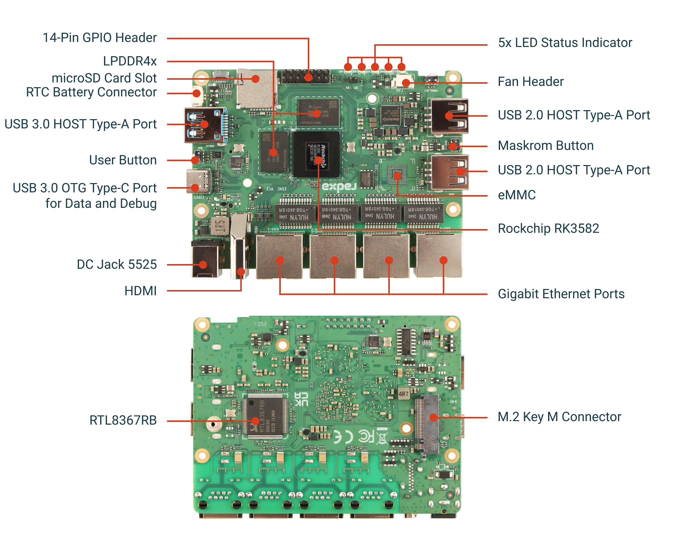
Front Interfaces:
- 4 Gigabit Network Interfaces (RJ45)
- 1 USB 3.0 Type-A Interface
- 2 USB 2.0 Type-A Interfaces
- 1 USB 3.0 Type-C (OTG) Interface
- 1 HDMI 2.1 Output Interface
- 1 DC 12V Power Input Interface (5.5mm x 2.5mm)
Side and Internal Interfaces:
- microSD Card Slot
- M.2 M-Key Slot (PCIe 2.1)
- 14-Pin GPIO Expansion Interface
- Fan and RTC Battery Interfaces
The following will detail the specifications, connection methods, and application recommendations for each interface.
microSD Card Slot
Interface Specifications
E54C is equipped with a standard microSD card slot, supporting hot-swapping functionality, which can be used for system booting or storage expansion.
| PIN | Name | Function Description |
|---|---|---|
| 1 | SDMMC_D2 | SD Card Data Line 2 |
| 2 | SDMMC_D3 | SD Card Data Line 3 |
| 3 | SDMMC_CMD | SD Card Command Line |
| 4 | VCC_3V3 | 3.3V Power Supply |
| 5 | SDMMC_CLK | SD Card Clock Signal |
| 6 | GND | Ground |
| 7 | SDMMC_D0 | SD Card Data Line 0 |
| 8 | SDMMC_D1 | SD Card Data Line 1 |
| 9 | SDMMC_DETN | SD Card Insertion Detection |
| 10 | GND | Ground |
| 11 | GND | Ground |
| 12 | GND | Ground |
| 13 | GND | Ground |
Usage Guide
- Supported Card Types: Compatible with microSD/microSDHC/microSDXC storage cards
- Recommended Specifications: Recommend using Class 10/UHS-I or higher specification cards for better performance
- Maximum Capacity: Theoretically supports up to 2TB microSDXC cards, practically tested to support 512GB
Main Application Scenarios
- System Boot: E54C can boot operating systems from a microSD card, which is the most common usage
- Data Storage: Can be used for storage expansion in existing systems (e.g., when booting from eMMC)
- System Backup: Can be used to backup current system and data
For production environments or systems that need to run 24/7, it is recommended to use eMMC or M.2 SSD as the primary storage and boot device, as they provide better stability and read/write durability. microSD cards are suitable for temporary storage and development testing scenarios.
USB Interfaces
E54C provides three different types of USB interfaces to meet various peripheral connection needs.
USB 3.0 HOST Type-A Interface
This is a standard USB 3.0 interface, supporting data transfer rates up to 5Gbps.
| PIN | Name | Function Description |
|---|---|---|
| 1 | VCC5V0_USB | 5V Power Output, maximum 500mA |
| 2 | USB3_HOST_DM | USB 2.0 Data Line Negative |
| 3 | USB3_HOST_DP | USB 2.0 Data Line Positive |
| 4 | GND | Ground |
| 5 | USB3_SSRX1N | USB 3.0 High-Speed Receive Line Negative |
| 6 | USB3_SSRX1P | USB 3.0 High-Speed Receive Line Positive |
| 7 | GND | Ground |
| 8 | USB3_SSTX1N | USB 3.0 High-Speed Transmit Line Negative |
| 9 | USB3_SSTX1P | USB 3.0 High-Speed Transmit Line Positive |
Application Recommendations:
- High-speed external storage devices (SSD/HDD)
- High-bandwidth network adapters
- USB 3.0 compatible peripherals (cameras, capture cards, etc.)
USB 2.0 HOST Type-A Interface
E54C is equipped with two USB 2.0 interfaces, supporting data transfer rates up to 480Mbps.
| PIN | Name | Function Description |
|---|---|---|
| 1 | VCC5V0_USB | 5V Power Output, maximum 500mA |
| 2 | USB2_HOST_DM | USB 2.0 Data Line Negative |
| 3 | USB2_HOST_DP | USB 2.0 Data Line Positive |
| 4 | GND | Ground |
Application Recommendations:
- Mouse, keyboard, and other input devices
- Low-bandwidth peripherals (printers, scanners, etc.)
- USB 2.0 compatible external devices
USB 3.0 OTG Type-C Interface
The Type-C interface supports OTG functionality, allowing it to work in host or device mode, while also supporting serial debugging and DisplayPort video output.
| PIN | Name | Function Description |
|---|---|---|
| A1/B1 | GND | Ground |
| A4/B4 | VCC5V0_USB | 5V Power Supply |
| A5 | CC1 | CC-based Interface Configuration Channel 1 |
| A6/B6 | DP | Data Line Positive |
| A7/B7 | DN | Data Line Negative |
| B5 | CC2 | CC-based Interface Configuration Channel 2 |
| A8 | SBU1 | Auxiliary Channel 1 |
| B8 | SBU2 | Auxiliary Channel 2 |
| A2/B2 | SSTX+ | USB 3.0 High-Speed Transmit Line Positive |
| A3/B3 | SSTX- | USB 3.0 High-Speed Transmit Line Negative |
| B11 | SSRX+ | USB 3.0 High-Speed Receive Line Positive |
| B10 | SSRX- | USB 3.0 High-Speed Receive Line Negative |
| A11 | SSRX+ | USB 3.0 High-Speed Receive Line Positive |
| A10 | SSRX- | USB 3.0 High-Speed Receive Line Negative |
| A12/B12 | GND | Ground |
Application Scenarios:
- Serial Debugging: Can be used for system debugging and configuration, supporting system console access via UART
- OTG Device Mode: Can connect E54C to a computer as a USB device
- DP Display Output: Supports connecting to monitors through a Type-C to DisplayPort adapter cable
- All USB ports share a total current supply of 1.5A, with a recommended maximum of 500mA per port
- For high-power peripherals, it is recommended to use an externally powered USB hub
- The display output and USB 3.0 functionality of the Type-C port cannot be used simultaneously; one must be chosen based on needs
HDMI 2.1 Interface
Interface Specifications
E54C is equipped with a standard HDMI 2.1 interface, supporting video output up to 8K, with powerful video capabilities for various display applications.
| PIN | Name | Function Description |
|---|---|---|
| 1 | HDMI_TX2+ | HDMI High-Speed Data Transmission Channel 2 Positive |
| 2 | GND | Ground |
| 3 | HDMI_TX2- | HDMI High-Speed Data Transmission Channel 2 Negative |
| 4 | HDMI_TX1+ | HDMI High-Speed Data Transmission Channel 1 Positive |
| 5 | GND | Ground |
| 6 | HDMI_TX1- | HDMI High-Speed Data Transmission Channel 1 Negative |
| 7 | HDMI_TX0+ | HDMI High-Speed Data Transmission Channel 0 Positive |
| 8 | GND | Ground |
| 9 | HDMI_TX0- | HDMI High-Speed Data Transmission Channel 0 Negative |
| 10 | HDMI_TXC+ | HDMI Clock Signal Positive |
| 11 | GND | Ground |
| 12 | HDMI_TXC- | HDMI Clock Signal Negative |
| 13 | HDMI_CEC | Consumer Electronics Control Signal, for inter-device control |
| 14 | NC | Not Connected |
| 15 | HDMI_SCL | DDC Clock Line, for EDID information reading |
| 16 | HDMI_SDA | DDC Data Line, for EDID information reading |
| 17 | GND | Ground |
| 18 | VCC5V0_HDMI | 5V Power Output |
| 19 | HDMI_HPD | Hot-Plug Detection Signal |
Supported Resolutions and Formats
The HDMI 2.1 interface supports output in various resolutions and scales:
- 4K@60Hz: Most common high-definition output mode, suitable for most modern displays
- 4K@30Hz: For older displays or TVs
- 1080p@60Hz: Full HD mode, suitable for standard HD displays
- 8K@30Hz: Highest resolution mode, supporting next-generation 8K displays
Supported color formats:
- RGB 444
- YCbCr 444/422/420
- HDR10 support
Application Scenarios
- Digital Signage: Displaying information or advertisements in public places
- Monitoring Systems: Displaying multiple video surveillance feeds
- Visualization Interfaces: Displaying system status and network traffic data
- Media Player: Connecting to TVs or displays for multimedia content playback
- HDMI and Type-C (DisplayPort) can be connected simultaneously, but during use, one will be selected as the output based on system configuration
- It is recommended to use high-quality HDMI cables to ensure stable transmission of high-resolution signals
- Although 8K is supported, 4K@60Hz is sufficient for most practical applications
Gigabit Ethernet Interfaces
Interface Specifications
E54C is equipped with 4 gigabit Ethernet ports, which are the core functional components of the product, supporting various network application scenarios. The following is the pin definition for the standard RJ45 interface:
| PIN | Name | Function Description |
|---|---|---|
| 1 | ETH_TXP | Gigabit Ethernet Transmit Data Positive |
| 2 | ETH_TXN | Gigabit Ethernet Transmit Data Negative |
| 3 | ETH_RXP | Gigabit Ethernet Receive Data Positive |
| 4 | NC | Not Connected |
| 5 | NC | Not Connected |
| 6 | ETH_RXN | Gigabit Ethernet Receive Data Negative |
| 7 | NC | Not Connected |
| 8 | NC | Not Connected |
Gigabit Network Controller
The gigabit network interfaces of E54C are driven by the network controller integrated in the Rockchip RK3582 SoC, with main features including:
- Full-Duplex Gigabit Ethernet: Each port supports 10/100/1000 Mbps rates
- MDI/MDIX Auto-Detection: Automatically identifies straight-through and crossover cables
- IEEE 802.3 Compatible: Supports standard Ethernet protocols
- Hardware Flow Control: Supports IEEE 802.3x flow control
- Internal MAC Address: Each port is assigned an independent MAC address
Network Configuration Scenarios
The four gigabit Ethernet ports allow flexible configuration of various network topologies:
1. Multi-WAN Router Configuration
Multiple ports can be configured as WAN interfaces to achieve:
- Multi-line load balancing
- Link aggregation
- Multi-ISP backup connections
2. Network Hub Configuration
Configure all ports in switch mode:
- Network segmentation (VLAN)
- QoS priority control
- Port mirroring and monitoring
3. Combination Mode
The most common configuration: 1 WAN + 3 LAN ports:
- 1 port connected to upstream router/modem
- 3 ports used for internal network device connections
Usage Recommendations
- It is recommended to use CAT 5e or higher specification Ethernet cables to achieve full gigabit performance
- Multi-WAN configuration requires specialized routing software support, such as iStoreOS or OpenWrt
- Pay attention to heat dissipation issues when running high-traffic network applications
For applications requiring powerful network performance (such as enterprise routers, gateways, etc.), port bonding can be configured to increase bandwidth and reliability. These advanced features can be easily configured in iStoreOS or OpenWrt.
M.2 M Key Interface
| PIN | Name |
|---|---|
| 1 | GND |
| 2 | VCC3V3_PCIE |
| 3 | GND |
| 4 | VCC3V3_PCIE |
| 5 | GND |
| 6 | NC |
| 7 | GND |
| 8 | NC |
| 9 | GND |
| 10 | NC |
| 11 | GND |
| 12 | NC |
| 13 | GND |
| 14 | NC |
| 15 | GND |
| 16 | NC |
| 17 | GND |
| 18 | NC |
| 19 | GND |
| 20 | NC |
| 21 | GND |
| 22 | NC |
| 23 | GND |
| 24 | NC |
| 25 | GND |
| 26 | NC |
| 27 | GND |
| 28 | NC |
| 29 | GND |
| 30 | NC |
| 31 | GND |
| 32 | NC |
| 33 | GND |
| 34 | NC |
| 35 | GND |
| 36 | NC |
| 37 | GND |
| 38 | NC |
| 39 | VCC3V3_PCIE |
| 40 | NC |
| 41 | VCC3V3_PCIE |
| 42 | NC |
| 43 | GND |
| 44 | NC |
| 45 | NC |
| 46 | NC |
| 47 | GND |
| 48 | NC |
| 49 | GND |
| 50 | PCIE_CLKREQ_N |
| 51 | GND |
| 52 | PCIE_WAKE_N |
| 53 | GND |
| 54 | PCIE_REFCLK_P |
| 55 | PCIE_REFCLK_N |
| 56 | NC |
| 57 | GND |
| 58 | PCIE_RX_N |
| 59 | PCIE_RX_P |
| 60 | GND |
| 61 | GND |
| 62 | PCIE_TX_N |
| 63 | PCIE_TX_P |
| 64 | GND |
| 65 | GND |
| 66 | NC |
| 67 | NC |
| 68 | PCIE_RST_N |
| 69 | GND |
| 70 | NC |
| 71 | GND |
| 72 | NC |
| 73 | GND |
| 74 | NC |
| 75 | GND |
M.2 SSD Support
E54C's M.2 slot supports M.2 2280 NVMe SSDs via PCIe 2.1 interface (1 lane, x1), with the following specifications:
- Interface Type: PCIe Gen2 x1, theoretical bandwidth up to 5Gbps
- SSD Form Factors: Compatible with M.2 2280 (80mm length)
- Protocol Support: NVMe protocol SSDs are supported
- Power Supply: The slot provides 3.3V power
Performance Optimization
- For optimal I/O performance, it's recommended to use high-quality NVMe SSDs with good sequential read/write capabilities
- The device firmware is optimized for popular NVMe SSD models, ensuring maximum compatibility
- In performance-critical applications, the disk IO scheduler can be adjusted for specific workloads
GPIO Expansion Interface
The 14-pin GPIO header provides access to various low-level interfaces:
| PIN | Name |
|---|---|
| 1 | VCC_3V3_S0 |
| 2 | VCC5V0 |
| 3 | I2C7_SDA_M3 |
| 4 | VCC5V0 |
| 5 | I2C7_SCL_M3 |
| 6 | GND |
| 7 | UART8_TX_M0 |
| 8 | SPI0_MOSI_M2 |
| 9 | UART8_RX_M0 |
| 10 | SPI0_MISO_M2 |
| 11 | I2C6_SCL_M0 |
| 12 | SPI0_SCK_M2 |
| 13 | I2C6_SDA_M0 |
| 14 | SPI0_CS0_M2 |
Additional Interfaces
- Fan Connector: 2-pin connector for connecting a 5V cooling fan
- RTC Battery Connector: For connecting a backup battery to maintain the real-time clock
- Recovery/Reset Buttons: Located on the board for system recovery or reset operations
Hardware Design Considerations
Thermal Management
E54C's aluminum case provides excellent passive cooling. For high-load applications:
- Ensure adequate airflow around the device
- For intensive workloads or hot environments, connect a fan to the dedicated fan header
- Keep ambient temperature below 35°C for optimal performance
Power Requirements
- Input Voltage: 12V DC (±5%)
- Power Consumption:
- Idle: ~5W
- Typical load: ~8-12W
- Full load with NVMe SSD: up to 15W
- Always use the recommended power adapter (12V/2A or higher)
Reliability Features
- Overvoltage protection
- Overcurrent protection
- Thermal throttling to prevent overheating
- Watchdog timer for system stability
Development Recommendations
For optimal use of E54C's hardware capabilities:
- Use iStoreOS or OpenWrt for network-focused applications
- Debian for general computing and AI development
- Custom Linux builds for specialized applications
- Take advantage of the NPU for AI processing, freeing CPU resources for other tasks
Conclusion
The Radxa E54C provides a powerful platform for edge computing and networking applications, with its combination of processing power, network interfaces, and expansion capabilities. This hardware interface reference will help you utilize the full potential of the device in your projects.