PC Enclosure Installation Guide
Case Compatibility Requirements
The Radxa O6 adopts the Mini-ITX form factor (170mm × 170mm) and is compatible with standard Mini-ITX chassis. When selecting a chassis, please ensure:
- At least 25mm of clearance above the motherboard to accommodate cooling components
- The chassis has good thermal ventilation design
- If using an ATX power supply, the chassis must support standard ATX power supplies
- Front panel interfaces must be compatible with the motherboard
- Sufficient space inside the chassis for PCIe device installation (if needed)
Cooling Installation
The Radxa O6 comes with a pre-installed heatsink and fan by default. If you wish to replace the heatsink, please refer to the following instructions. For the disassembly guide of the pre-installed heatsink, please check Heatsink 8420B Disassembly.
CPU Cooling
- Mounting hole spacing: 75mm × 75mm
- Supported types: Active and passive cooling
- Recommended TDP handling capacity: 30W
Fan Installation
- 4-pin PWM fan connector
- Supports speed monitoring
- Fan control available through UEFI
Cooling Notes
- Apply an appropriate amount of thermal paste when replacing the heatsink
- Ensure good contact between the heatsink and SoC
- Maintain good airflow inside the chassis to prevent thermal throttling
Temperature Monitoring
- Operating temperature range: 0°C ~ 40°C
- Thermal throttling may occur above 80°C
- Monitor temperatures using system tools
Motherboard Installation
Preparing the Chassis
- Remove the side panel and any protective covers from the chassis
- Install Mini-ITX standoffs in the chassis
- Ensure proper grounding between the chassis and motherboard
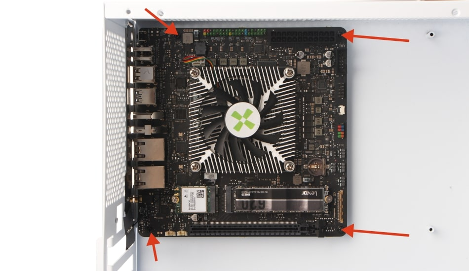
Installing the Motherboard
- Align the motherboard with the pre-installed standoffs
- Match the I/O shield with the rear chassis opening
- Secure the motherboard using four M3 screws:
- First, partially tighten two diagonal screws.
- Check the motherboard position; if adjustment is needed, loosen the screws, adjust, and retighten.
- Then tighten the remaining two screws to ensure the motherboard is firmly secured.
- Recommended torque: 0.5 Nm
Front Panel Connections
Follow these steps to connect the front panel interfaces:
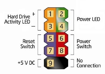
1. Power Button & LED Headers
2-4: Power LED +/-
6-8: Power Switch
5-7: Reset Button
1-3: HDD LED
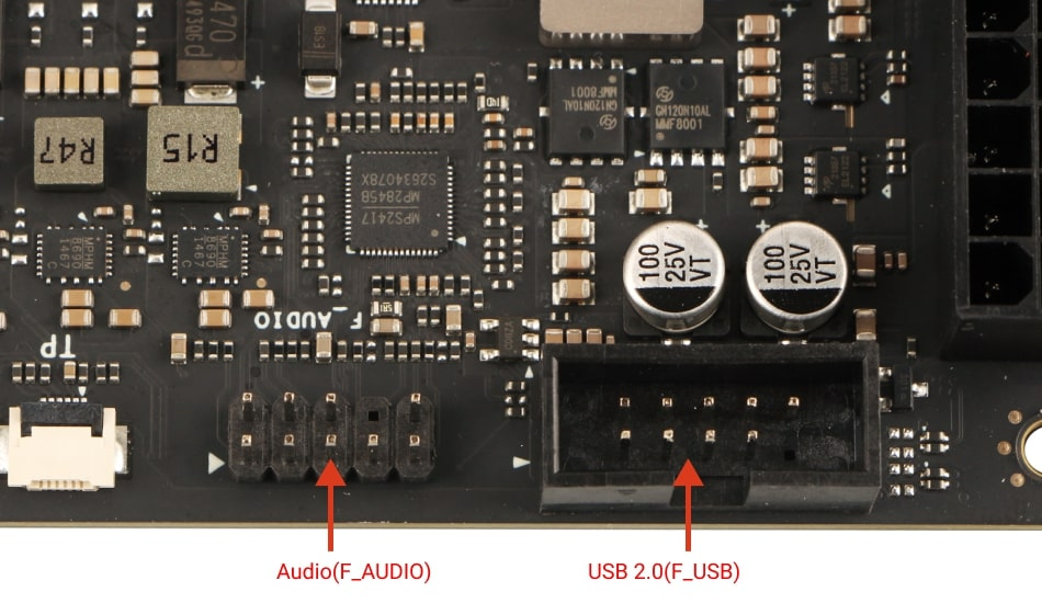
2. USB 2.0 Headers
- Supports two USB 2.0 ports
- Pin 1 is marked with a triangle
- Pay attention to the orientation when connecting
3. Audio Header
- HD Audio compatible
- Supports front panel 3.5mm audio jack
- Pin 1 indicates the orientation
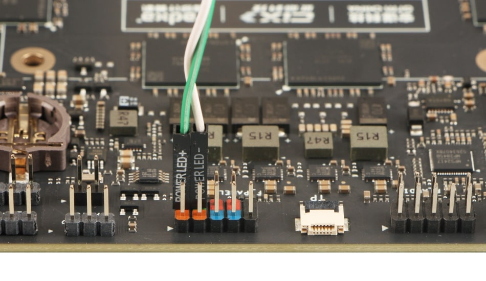
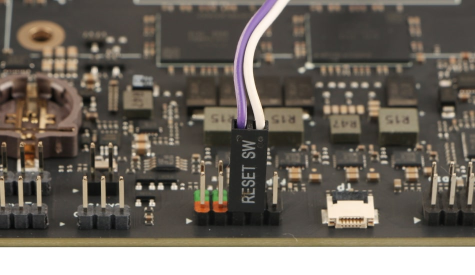
How to Install Power Button, Reset Button, and LED Headers
-
Locate the F_PANEL header on the Radxa O6 motherboard, which is used to connect the power button, reset button, power LED, and HDD LED.
-
Follow the diagrams below to correctly connect each header, paying attention to polarity.
-
Power LED
-
Power Button
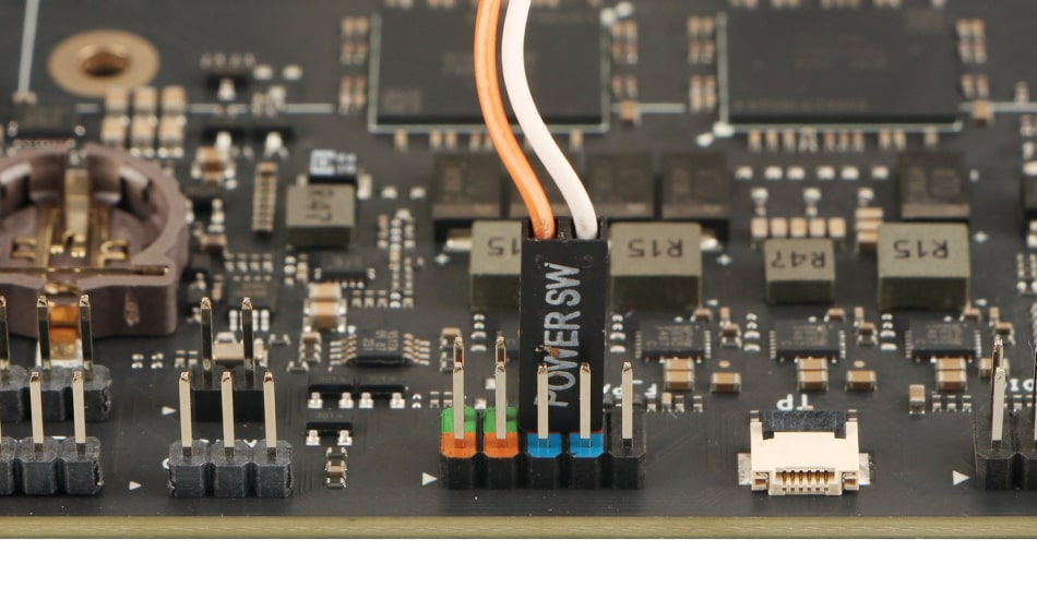
-
Reset Button
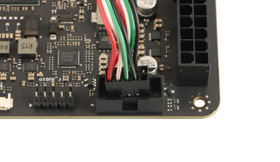
How to Install Front USB 2.0 Header
-
Locate the F_USB header on the motherboard, which is used to connect the front panel USB 2.0 ports.
-
This header features a foolproof design: it's actually a 10-pin socket with one pin missing to prevent incorrect insertion. When installing, align the missing pin and insert the connector.
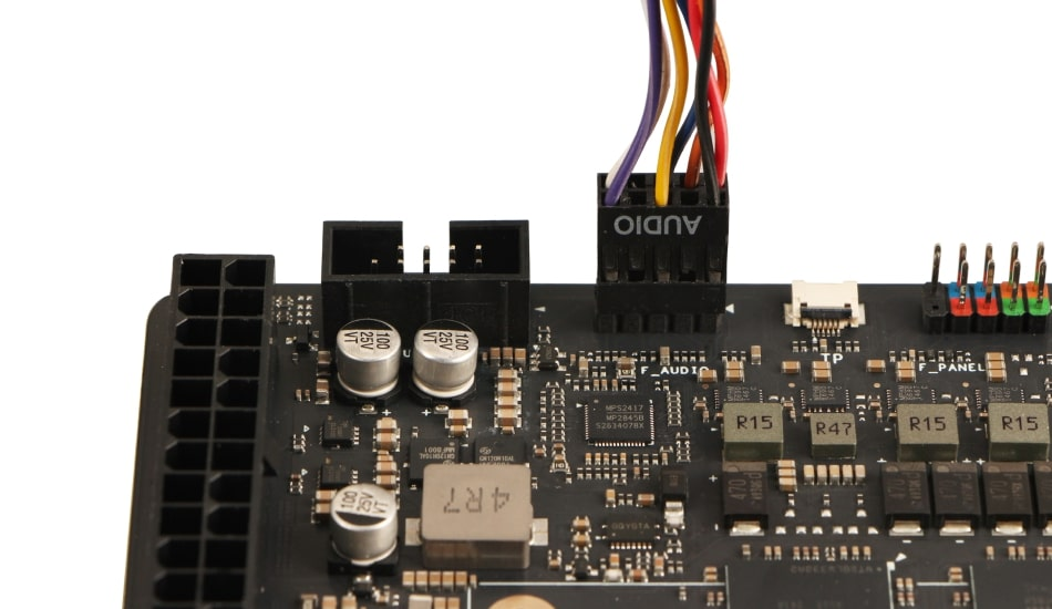
How to Install Front Audio Header
-
Locate the F_AUDIO header on the motherboard, which is used to connect the front panel audio port.
-
This header also follows a 10-pin design but actually only has 9 pins. When installing, align the missing pin for correct insertion.
Additional Component Installation
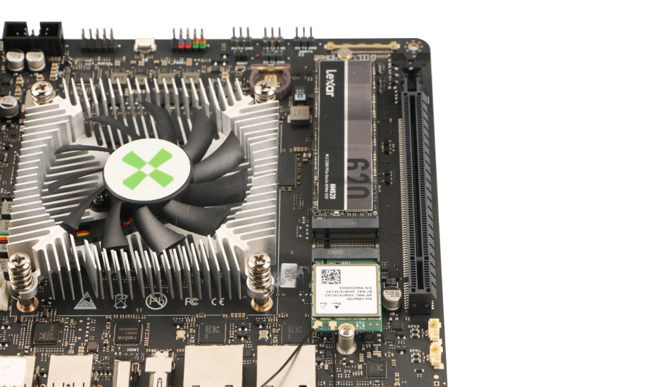
1. Storage Device Installation
- M.2 M-Key Slot: For NVMe SSD
- Supports PCIe Gen4 x4
- Compatible with 2280 form factor
- Use the retention screw for installation
2. Wireless Network Card Installation
- M.2 E-Key Slot:
- Supports PCIe Gen4 x2 + USB
- Compatible with standard WiFi/Bluetooth modules
- If using a wireless network card, install the antennas
3. PCIe Device Installation
- x16 Slot (actually operates at x8 Gen4)
- Supports full-length PCIe devices
- Ensure sufficient installation space in the chassis
- Secure the device with bracket screws
Power Connections
The Radxa O6 supports multiple power input methods:
1. ATX Power Supply (Recommended for Desktop Use)
- Connect the 24-pin ATX power connector
- Ensure the power supply is at least 65W
- Recommendation: Use 120W or higher for optimal performance
2. Power Connection Sequence
- Connect the power supply to the motherboard
- Connect the power supply to the AC outlet
- Turn on the power supply before booting the system
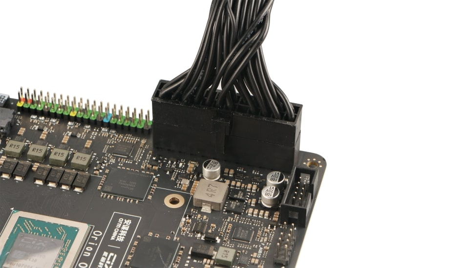
Installing the ATX Power Connector
-
Before installation, ensure the ATX power supply is unplugged to prevent hardware damage.
-
Align the ATX power connector with the 24-pin ATX power socket on the motherboard, ensuring the notch on the connector matches the protrusion on the socket for correct orientation.
-
Insert firmly with both hands, ensuring level insertion without tilting. You should hear a slight "click" when properly installed.
Installation Completion Checklist
- All screws are properly tightened
- Power connections are secure
- Front panel headers are correctly connected
- Cooling solution is properly installed
- Storage devices are securely mounted
- PCIe devices are firmly seated
- No loose cables or components inside the chassis