PC Enclosure Installation Guide
Case Compatibility Requirements
The Radxa Orion O6 is designed in the Mini-ITX form factor (170mm × 170mm) and is compatible with standard Mini-ITX cases. When selecting a case, ensure:
- Minimum clearance of 25mm above the motherboard for components
- Adequate ventilation for proper cooling
- Support for standard ATX power supply if using ATX power
- Front panel connectors compatibility
- Sufficient space for PCIe cards if needed
Cooling Installation
The Radxa Orion O6 comes with a heatsink and fan pre‑installed. If you want to use your own coolers, refer to the notes below. For instructions on assembling and disassembling the pre‑installed Heatsink 8420B, check the Heatsink Usage.
CPU Cooling
- Mounting holes: 75mm × 75mm pattern
- Support: Both active and passive cooling
- Recommended TDP handling: 30W
Fan Installation
- 4‑pin PWM fan header
- Supports speed monitoring
- Fan control through UEFI settings
Thermal Considerations
- Apply thermal paste if using a heatsink
- Ensure proper contact with SoC
- Maintain airflow path in the case
Temperature Monitoring
- Operating range:0°C ~ 40°C
- Throttling may occur above 80°C
- Monitor temperatures through system tools
Motherboard Installation
Prepare the Case
- Remove side panels and any protective covers.
- Install standoffs in the correct Mini‑ITX mounting positions.
- Ensure proper grounding between the case and motherboard.
Mount the Motherboard
- Align the motherboard with pre‑installed standoffs.
- Match the I/O shield with the rear case opening.
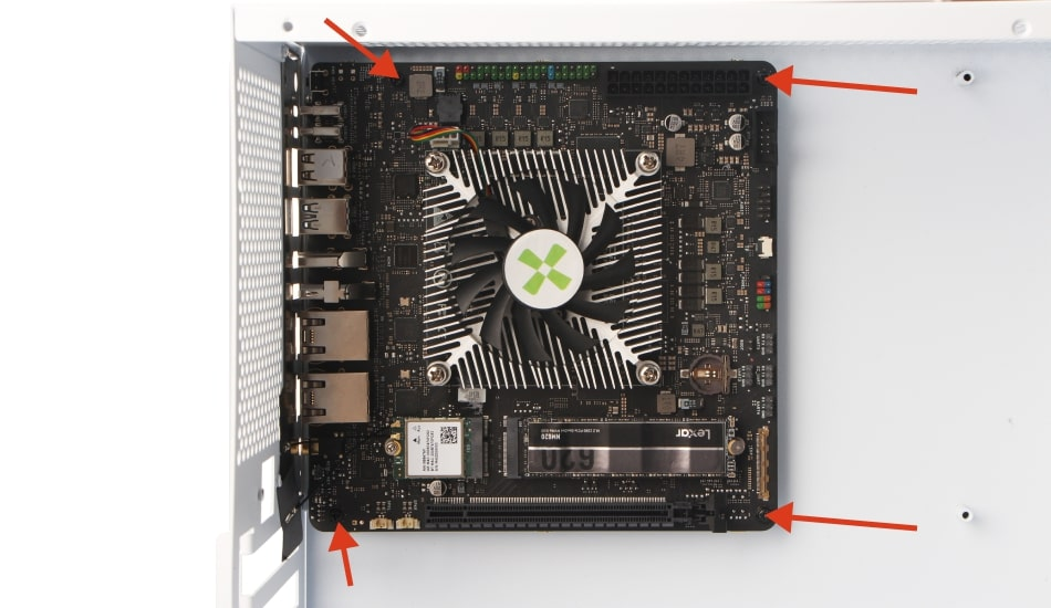
- Secure the motherboard using 4 M3 screws in the following order:
- First, insert and slightly tighten two diagonal screws into the respective holes.
- Check the motherboard’s position. If adjustment is needed, loosen the tightened screws, adjust, and retighten.
- Then, tighten the other two diagonal screws in sequence to secure the motherboard firmly.
- Recommended torque:0.5 Nm
Front Panel Connections
Please connect the case front panel as follows:
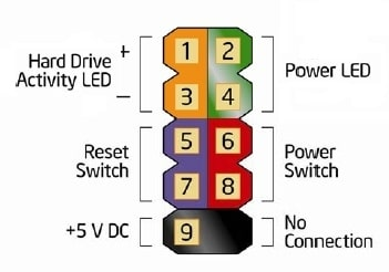
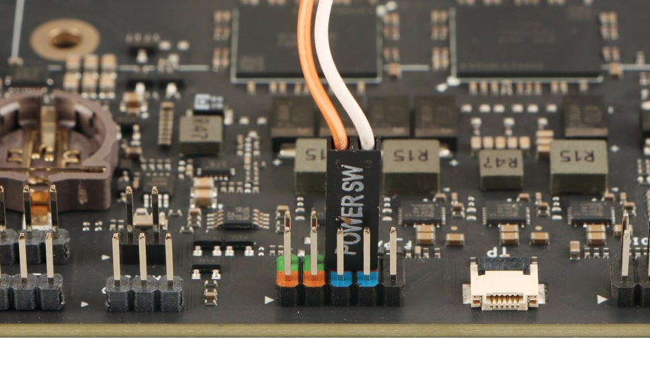
1. Power Button & LED Header
2-4: Power LED +/-
6-8: Power Button
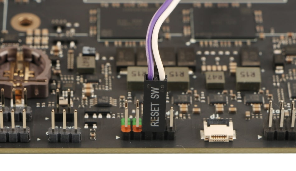
5-7: Reset Button
1-3: HDD LED
2. USB 2.0 Headers
- Support for two USB 2.0 ports
- Pin 1 marked with triangle
- Observe correct orientation
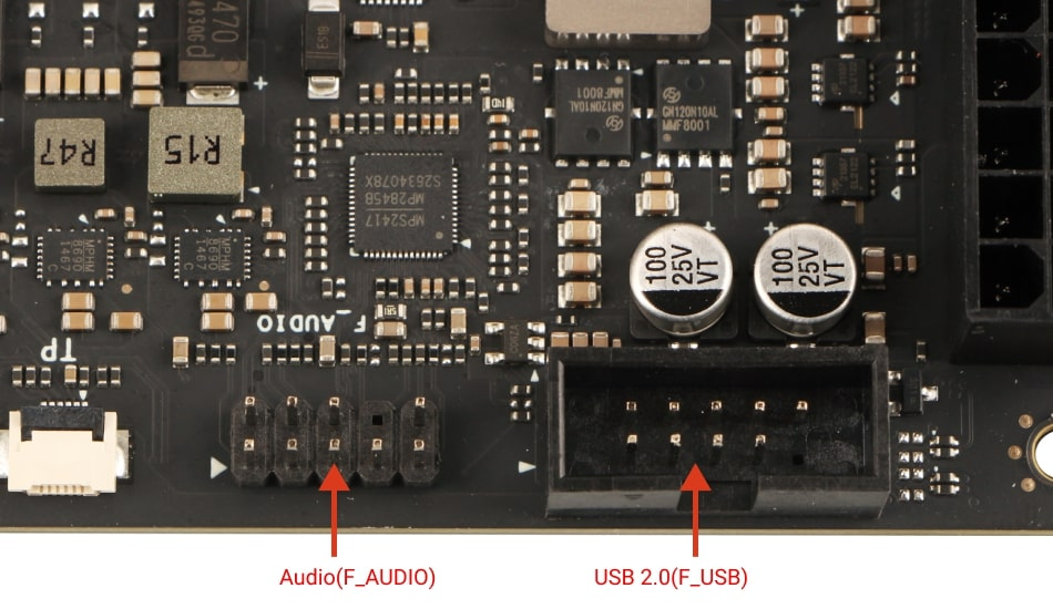
3. Audio Header
- HD Audio compatible
- Supports front panel audio jacks
- Pin 1 marked for orientation
How to Install the Power Button, Reset Button and LED Header Interface
-
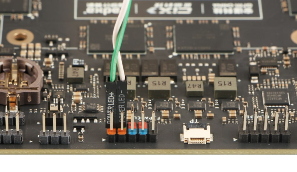
Locate the F_PANEL interface on the Orion O6 motherboard. The front panel interface (F_PANEL) of the Orion O6 is used to connect the power supply,the reset button, the power status light and the hard disk status light, so as to achieve the corresponding functions and status display.
-
As shown in the figure, insert the corresponding interfaces one by one. During the operation, be sure to pay attention to the positive and negative poles.
-
Power LED
-
Power Button
-
Reset Button
How to Install the Front USB 2.0 Interface
-
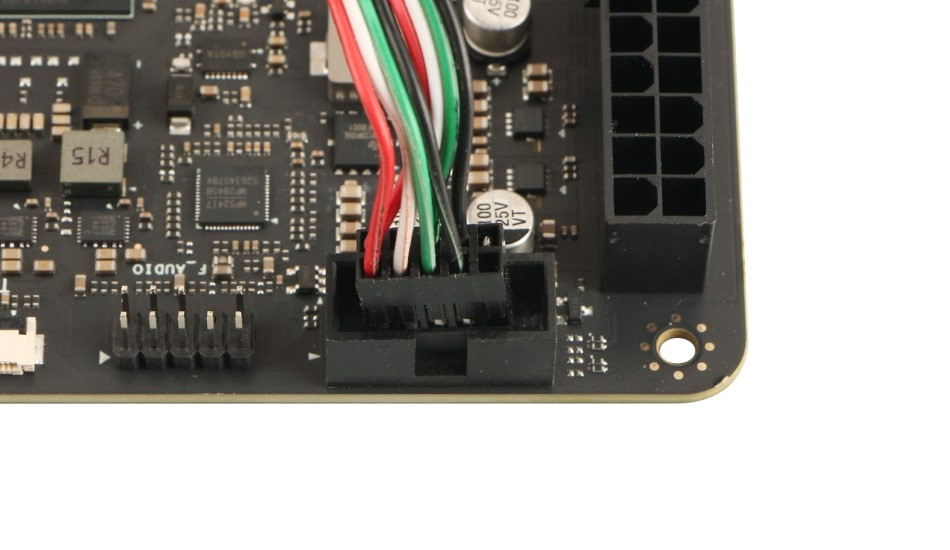
Locate the F_USB interface on the Orion O6 motherboard. The front USB 2.0 interface (F_USB) of the Orion O6 is used to connect to the USB 2.0 ports.
-
When carrying out the installation, please pay attention to the F_USB interface. This interface has distinct features: it generally appears as a 10‑pin socket, but in fact, it only has 9 pins. If you observe carefully, you will find that one pin is missing, which can effectively avoid the risk of incorrect insertion. During the installation process, you just need to precisely align the corresponding plug with the position of this missing pin and then insert it smoothly to ensure that the connection is accurate.
How to Install the Front Audio Interface
-
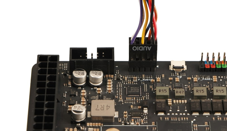
Locate the F_AUDIO interface on the Orion O6 motherboard. The front audio interface (F_AUDIO) of the Orion O6 is used to connect to the audio ports.
-
When carrying out the installation, please pay attention to the F_AUDIO interface. This interface has distinct features: it generally appears as a 10‑pin socket, but in fact, it only has 9 pins. If you observe carefully, you will find that one pin is missing, which can effectively avoid the risk of incorrect insertion. During the installation process, you just need to precisely align the corresponding plug with the position of this missing pin and then insert it smoothly to ensure that the connection is accurate.
Additional Components
1. Storage Installation
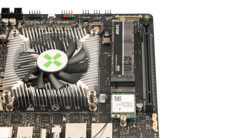
- M.2 M-Key slot for NVMe SSD
- Supports PCIe Gen4 x4
- 2280 Form Factor
- Secure with mounting screw
2. Wireless Card Installation
- M.2 E-Key Slot:
- Supports PCIe Gen4 x2 + USB
- Compatible with standard WiFi/BT modules
- Attach antennas if required
3. PCIe Card Installation
- x16 Slot (Operating at x8 Gen4)
- Supports full-length PCIe devices
- Ensure proper case clearance
- Secure with bracket screws
Power Connection
The Orion O6 supports multiple power input methods:
**1. ATX Power Supply (Recommended for Desktop Usage) **
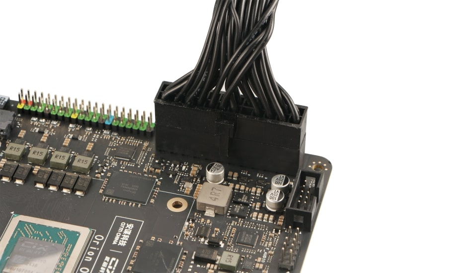
- Connect the 24‑pin ATX power connector
- Ensure PSU can provide at least 65W
- Recommended: 120W or higher for full performance
2. Power Sequence
- Connect power supply to motherboard
- Connect power supply to AC outlet
- Turn on power supply before system power
How to install the ATX Power Interface
-
Before installing, ensure that the ATX power is disconnected. This is to avoid damage to the hardware caused by improper operation.
-
Align the ATX power plug with the 24‑Pin ATX power socket on the motherboard, making sure that the notch on the plug matches the protrusion on the socket to ensure the correct orientation. After confirming the orientation, hold the plug with both hands and gently insert it along the direction of the socket with a steady and even force. During the insertion process, keep the plug horizontal and avoid tilting it to ensure that each pin can smoothly slide into the corresponding socket hole.
-
When you hear a slight “click” sound and the plug fits completely against the socket and can no longer be inserted further, it indicates that the plug has been properly installed.
Post‑Installation Checklist
- All screws properly tightened
- Power connections secure
- Front panel headers correctly oriented
- Cooling solution properly mounted
- Storage devices secured
- PCIe cards fully seated
- No loose cables or components