Hardware Information
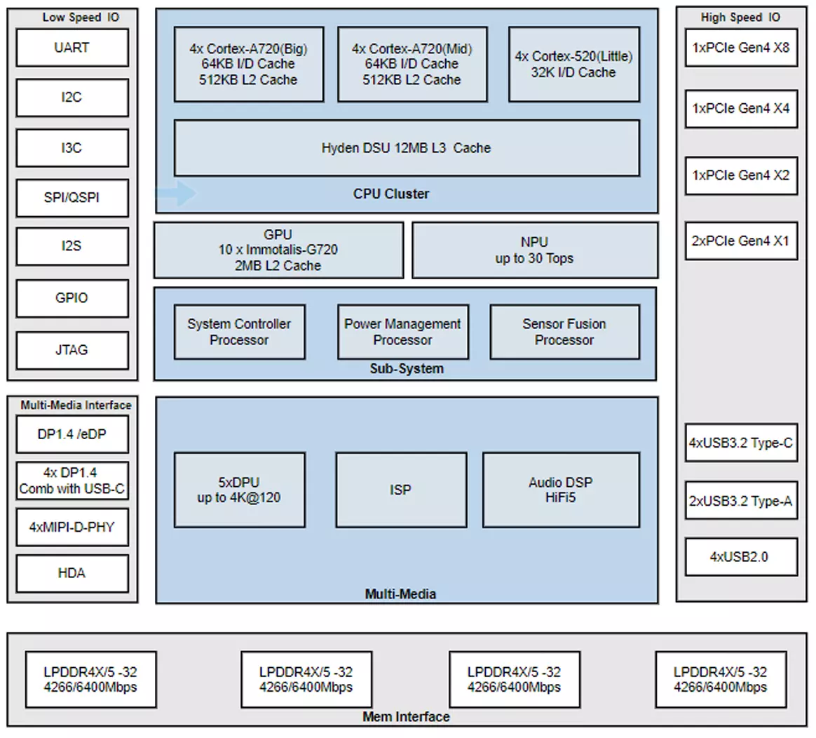
Chip Block Diagram
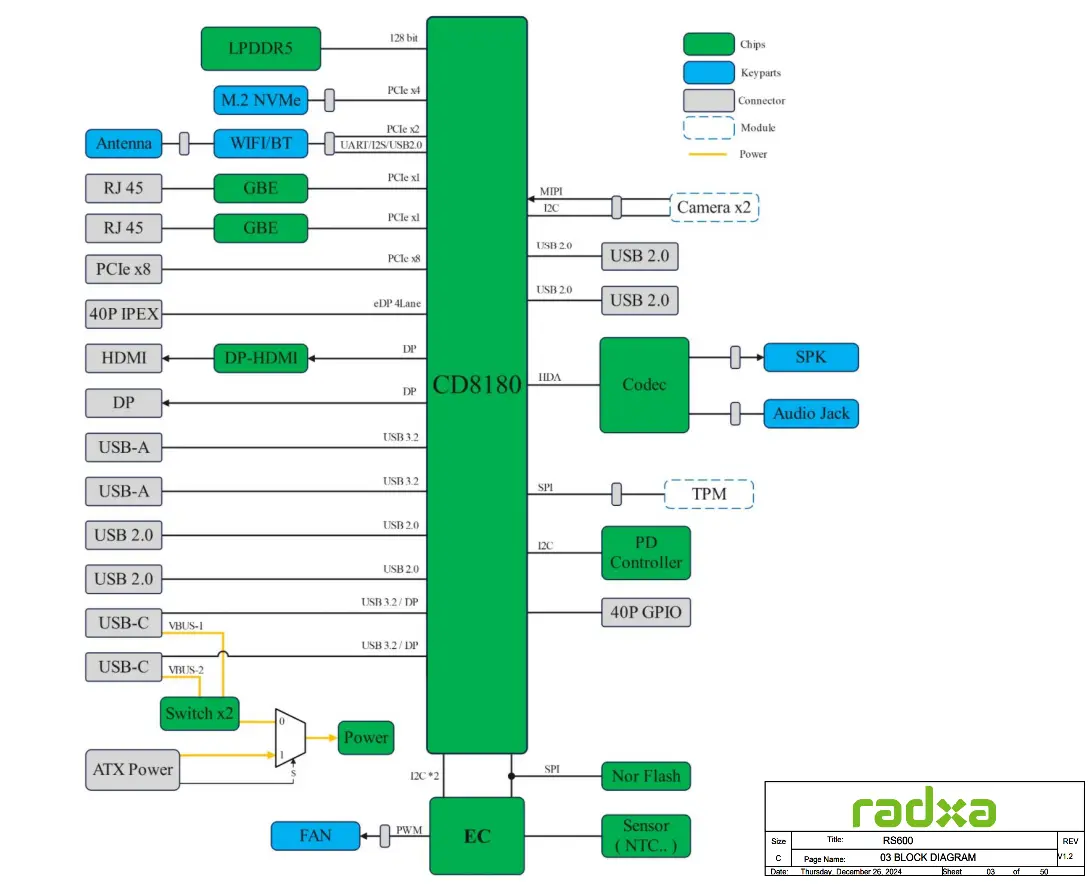
System Block Diagram
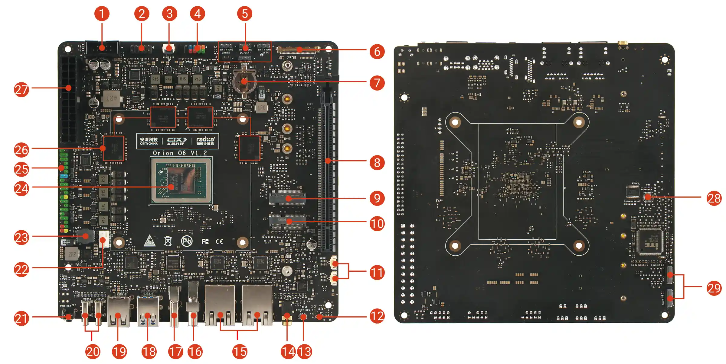
Interface Description
| No. | Description | No. | Description | No. | Description |
|---|---|---|---|---|---|
| 1 | USB 2.0 (Front Panel) | 11 | 2x Speaker Interface | 21 | Power Button |
| 2 | Audio Interface (Front Panel) | 12 | Status Indicator | 22 | 4-Pin Fan Connector - Supports PWM Speed Control & Monitoring |
| 3 | Touch Panel Interface | 13 | Reset Button | 23 | BIOS Flash Socket |
| 4 | Multi-function Interface (Front Panel) - Power/LED/Reset | 14 | 3.5 mm Headphone Jack | 24 | CIX P1 SoC |
| 5 | UART Interface | 15 | 2x 5G Ethernet | 25 | 40-Pin GPIO Header |
| 6 | eDP Interface | 16 | DisplayPort | 26 | LPDDR5 |
| 7 | RTC Battery Holder | 17 | HDMI Port | 27 | ATX Power Connector |
| 8 | PCIe x16 Slot (PCIe Gen x4) | 18 | 2x USB 3.2 Type-A | 28 | TPM (Unsoldered) |
| 9 | M.2 M Key Slot | 19 | 2x USB 2.0 Type-A | 29 | 2x MIPI CSI 4-lane |
| 10 | M.2 E Key 2230 Slot | 20 | 2x USB Type-C - 20V Type-C Power Delivery (PD) Supported - Supports DP Alt Mode |
Power Button
Primarily used to control the motherboard's power switch.
- When the motherboard is powered off, press the power button to start the motherboard
- When the motherboard is running, a short press triggers a power event that may display a power menu or put the system into suspend mode, depending on OS settings
- Press and hold the power button for 4 seconds to force a shutdown
Reset Button
Mainly controls the motherboard's system reset. A short press will restart the system.
Status Indicators
Two status indicators are onboard.
- Green LED: Indicates power status
- Blue LED: Indicates system status
- Solid blue: BIOS has booted normally
- Blinking blue: Operating system has booted normally
USB Type-C Ports
Two USB 3.2 Type-C ports are onboard, supporting data transfer speeds up to 10Gbps. Both support power delivery, and one supports DP Alt Mode.
- Recommended to use the Radxa PD 65W Power Adapter to power the motherboard
- Either USB Type-C port can power the motherboard. If two power sources are connected simultaneously, the first PD power source connected will power the motherboard
- Each USB Type-C port can provide up to 3A of current to external devices
- USBC0 supports OTG mode, USBC1 supports HOST mode
USB Type-A Ports
Onboard 2x USB 2.0 Type-A ports, 2x USB 3.2 Type-A ports, and a front panel USB 2.0 interface.
- USB 2.0 Type-A: Maximum transfer rate of 480Mbps, all USB 2.0 ports share a total of 1.4A current
- USB 3.2 Type-A: Maximum transfer rate of 10Gbps, each port current limited to 1A
- USB 2.0 Interface (Front Panel)
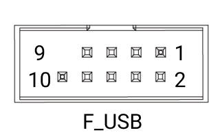
| Pin | Name | Description | Pin | Name | Description | Pin | Name | Description |
|---|---|---|---|---|---|---|---|---|
| 1 | 5V_1 | Power (+5V) | 2 | 5V_2 | Power (+5V) | 3 | USB_DM_1 | USB Data- |
| 4 | USB_DM_2 | USB Data- | 5 | USB_DP_1 | USB Data+ | 6 | USB_DP_2 | USB Data+ |
| 7 | GND | Ground | 8 | GND | Ground | 9 | - | Reserved/NC |
| 10 | GND | Ground |
HDMI Port
Onboard HDMI Type-A port, supports up to 4K@60Hz. HDMI CEC function is not supported.
DisplayPort
Onboard DisplayPort, supports up to 4K@120Hz with Multi-Stream Transport (MST) support.
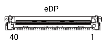
eDP Interface
Onboard eDP interface with 0.5mm pitch 40-Pin IPEX connector, directly connects to eDP panels, supporting up to 4K@60Hz.
| Pin | Name | Description | Pin | Name | Description | Pin | Name | Description |
|---|---|---|---|---|---|---|---|---|
| 1 | NC | No Connection | 2 | GND | Ground | 3 | 3N | eDP Lane 3 Negative |
| 4 | 3P | eDP Lane 3 Positive | 5 | GND | Ground | 6 | 2N | eDP Lane 2 Negative |
| 7 | 2P | eDP Lane 2 Positive | 8 | GND | Ground | 9 | 1N | eDP Lane 1 Negative |
| 10 | 1P | eDP Lane 1 Positive | 11 | GND | Ground | 12 | 0N | eDP Lane 0 Negative |
| 13 | 0P | eDP Lane 0 Positive | 14 | GND | Ground | 15 | AUXP | eDP Auxiliary Channel Positive |
| 16 | AUXN | eDP Auxiliary Channel Negative | 17 | GND | Ground | 18 | VDD1 | Power (+3.3V) |
| 19 | VDD2 | Power (+3.3V) | 20 | VDD3 | Power (+3.3V) | 21 | VDD4 | Power (+3.3V) |
| 22 | NC | No Connection | 23 | GND | Ground | 24 | GND | Ground |
| 25 | GND | Ground | 26 | GND | Ground | 27 | NC | No Connection |
| 28 | GND | Ground | 29 | GND | Ground | 30 | GND | Ground |
| 31 | GND | Ground | 32 | BL_EN | Backlight Enable | 33 | PWM | Backlight PWM Control |
| 34 | NC | No Connection | 35 | NC | No Connection | 36 | VBL1 | Backlight Power |
| 37 | VBL2 | Backlight Power | 38 | VBL3 | Backlight Power | 39 | VBL4 | Backlight Power |
| 40 | NC | No Connection | 41 | NC | No Connection | 42 | NC | No Connection |
| 43 | GND | Ground |
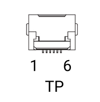
Touch Panel Interface
Primarily used for touchscreen integration, working with the eDP interface to provide a direct connection for touchscreens.
| Pin | Name | Description | Pin | Name | Description | Pin | Name | Description |
|---|---|---|---|---|---|---|---|---|
| 1 | Reset | Touch Controller Reset (3.3V) | 2 | VCC | Touch Panel Power (3.3V) | 3 | GND | Ground Connection |
| 4 | EINT | External Interrupt (3.3V) | 5 | SDA | I2C Data Line for Touch (3.3V) | 6 | SCL | I2C Clock Line for Touch (3.3V) |
| 7 | GND | Ground Connection | 8 | GND | Ground Connection |
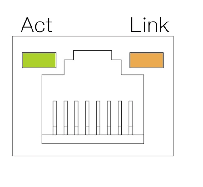
5G Ethernet Ports
Onboard dual 5G RJ45 Ethernet ports, supporting 10/100/1000/2500/5000 Mbps auto-negotiation.
| LED | State | Description |
|---|---|---|
| Orange | Solid | Link established (Device connected to network) |
| Green | Blinking | Data transmission in progress (Network activity) |
| Off | - | No link detected (Cable unplugged or network issue) |
Audio Interface
Onboard 3.5mm headphone jack and front panel audio interface.
Headphone Jack
Onboard 3.5mm headphone jack supporting both audio output and input.
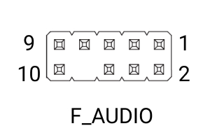
Audio Interface (Front Panel)
Supports front panel audio functionality for PC cases.
| Pin | Name | Description | Pin | Name | Description | Pin | Name | Description |
|---|---|---|---|---|---|---|---|---|
| 1 | MIC_INL | Microphone Input (Left) | 2 | GND | Ground | 3 | MIC_INR | Microphone Input (Right) |
| 4 | GND | Ground | 5 | HP_OUT_R | Headphone Out (Right) | 6 | FRONT_MIC_JD | Front Panel Mic Jack Detect |
| 7 | GND | Ground | 8 | / | Reserved/NC | 9 | HP_OUT_L | Headphone Out (Left) |
| 10 | FRONT_HP_JD | Front Panel HP Jack Detect |
PCIe x16 Slot
Onboard full-size PCIe x16 slot, supporting PCIe Gen4 x8, compatible with high-performance graphics cards.
- Power Supply:
- Maximum 60W for PCIe slot when using ATX power supply
- Maximum 15W for PCIe slot when using USB Type-C power supply
Fan Connector
Onboard standard ATX 4-Pin fan connector with PWM control and tachometer support.
Note: The motherboard has silkscreen markings for easy identification and connection.
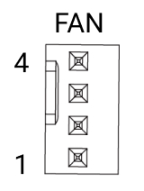
| Pin | Name | Description | Pin | Name | Description | Pin | Name | Description |
|---|---|---|---|---|---|---|---|---|
| 1 | GND | Ground | 2 | VCC12V | Power (12V) | 3 | TACH | Tachometer Signal (Fan Speed) |
| 4 | PWM | PWM Control Signal (3.3V) |
BIOS Flash Socket
Onboard BIOS flash chip socket for easy removal or replacement of the BIOS chip.
- Chip Compatibility: Supports SOP8 flash memory chips
- Chip Capacity: 8MB (64Mbit)
- Voltage Level: 1.8V
Notes:
- The circle corresponds to pin 1, and it is marked with a red circle on the diagram.
- The triangle corresponds to pin 1, and it is marked with a red triangle on the diagram.
| Pin | Name | Pin | Name | Pin | Name | Pin | Name |
|---|---|---|---|---|---|---|---|
| 1 | ROM_CS | 2 | ROM_MISO | 3 | ROM_WP | 4 | GND |
| 5 | ROM_MOSI | 6 | ROM_CLK | 7 | ROM_HOLD | 8 | ROM_VCC |
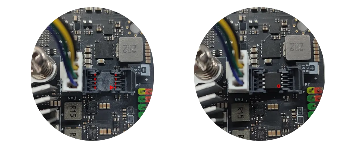
Non-essential operation, please do not remove the BIOS chip.
To remove and install the BIOS chip, users can refer to the Updating BIOS Firmware Tutorial section of the tutorial on how to use the programmer to update the BIOS firmware.
40-Pin GPIO Header
Onboard 40-Pin GPIO (General Purpose Input/Output) interface, providing highly flexible hardware expansion capabilities.
Users can connect various sensors, actuators, communication modules, displays, and other embedded peripherals through the 40-Pin GPIO interface, enabling rapid prototyping and functional verification in fields such as IoT, robotics, and industrial automation.
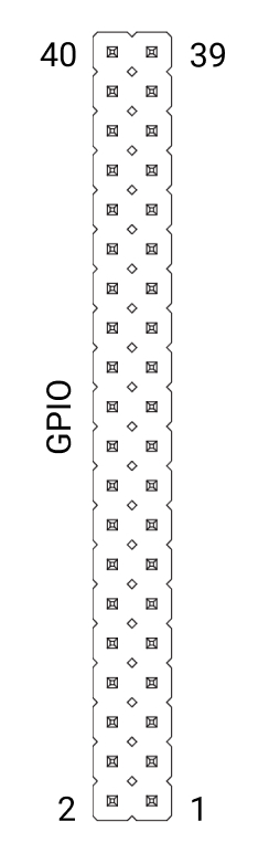
| Function3 | Function2 | Function1 | Pin# | Pin# | Function1 | Function2 | Function3 |
|---|---|---|---|---|---|---|---|
| 3.3V | 1 | 2 | 5V | ||||
| GPIO061 | I2C4_SDA | 3 | 4 | 5V | |||
| GPIO062 | I2C4_CLK | 5 | 6 | GND | |||
| GPIO071 | 7 | 8 | UART3_TXD | GPIO105 | |||
| GND | 9 | 10 | UART3_RXD | GPIO106 | |||
| GPIO095 | PWM0 | UART0_TXD | 11 | 12 | GPIO091 | I2S4_SCK_LB | |
| GPIO096 | PWM1 | UART0_RXD | 13 | 14 | GND | ||
| GPIO099 | FAN_OUT0 | UART1_TXD | 15 | 16 | UART1_RXD | FAN_TACH0 | GPIO100 |
| 3.3V | 17 | 18 | GPIO044 | ||||
| SPI2_MOSI | GMAC1_TXD3 | GPIO141 | 19 | 20 | GND | ||
| SPI2_MISO | GMAC1_TXD0 | GPIO138 | 21 | 22 | GPIO045 | ||
| SPI2_CLK | GMAC1_TX_CLK | GPIO142 | 23 | 24 | GPIO139 | SPI2_CS0 | |
| GND | 25 | 26 | GPIO140 | SPI2_CS1 | |||
| GPIO056 | I3C0_SDA | I2C2_SDA | 27 | 28 | I2C2_CLK | I3C0_SCL | GPIO055 |
| GPIO076 | I2S2_DATA_IN1 | 29 | 30 | GND | |||
| GPIO078 | I2S2_DATA_OUT1 | 31 | 32 | GPIO046 | |||
| GPIO079 | I2S2_DATA_OUT2 | 33 | 34 | GND | |||
| I2S4_WS_LB | GPIO092 | 35 | 36 | GPIO090 | I2S4_MCLK_LB | ||
| GPIO080 | I2S2_DATA_OUT3 | 37 | 38 | GPIO093 | I2S4_DATA_IN_LB | ||
| GND | 39 | 40 | GPIO094 | I2S4_DATA_OUT_LB |
ATX Power Connector
Onboard 24-pin ATX-compatible power connector for standard ATX power supply compatibility.
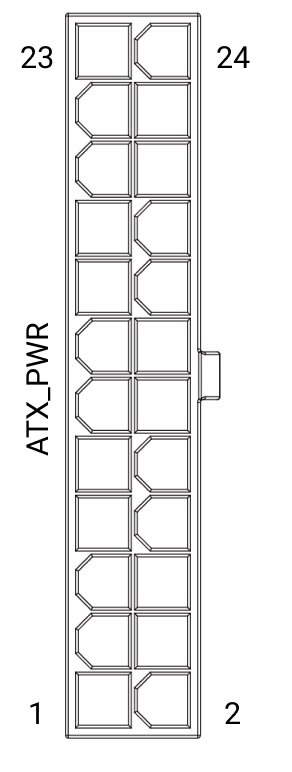
| Pin | Name | Description | Pin | Name | Description | Pin | Name | Description |
|---|---|---|---|---|---|---|---|---|
| 3 | GND | Ground | 5 | GND | Ground | 7 | GND | Ground |
| 8 | PWR_OK | Power Good (Logic High: 3.3V or 5V) | 9 | 5VSB | Standby Power (+5V, Always On) | 10 | 12V | Power (+12V) |
| 11 | 12V | Power (+12V) | 13 | NC | No Connection | 14 | NC | No Connection |
| 15 | GND | Ground | 16 | PS_ON | Power On (Active Low) | 17 | GND | Ground |
| 18 | GND | Ground | 19 | GND | Ground | 20 | NC | No Connection |
| 21 | NC | No Connection | 22 | NC | No Connection | 23 | NC | No Connection |
| 24 | GND | Ground |
M.2 M Key Slot
Onboard M.2 M Key slot supporting PCIe Gen4 x4, compatible with 2230/2242/2260/2280 M.2 NVMe SSDs for storage expansion.
M.2 E Key Slot
Onboard M.2 E Key slot supporting PCIe Gen4 x2, compatible with 2230 form factor WiFi/Bluetooth modules.
Multi-function Interface (Front Panel)
Onboard multi-function interface for front panel power button, reset button, and status indicators.
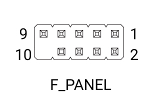
| Pin | Name | Description | Pin | Name | Description | Pin | Name | Description |
|---|---|---|---|---|---|---|---|---|
| 1 | SSD_LED+ | SSD Activity LED (+) | 2 | PWR_LED+ | Power LED (+) | 3 | SSD_LED- | SSD Activity LED (-) |
| 4 | PWR_LED- | Power LED (-) | 5 | RESET- | Reset Switch (-) | 6 | PWR_ON | Power On Signal |
| 7 | RESET+ | Reset Switch (+) | 8 | PWR_GND | Power Ground | 9 | RSV(5V) | Reserved (5V Power) |
| 10 | NC | No Connection |
UART Interfaces
Four dedicated UART interfaces for various debugging purposes.
- UART2: BIOS and OS debug logs
- UART4: Power management, voltage and frequency monitoring
- UART5: Secure BootROM debug logs
- EC UART: Onboard embedded controller debug logs
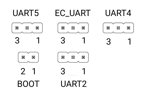
UART_x Pinout
| Pin | Name | Description | Pin | Name | Description | Pin | Name | Description |
|---|---|---|---|---|---|---|---|---|
| 1 | GND | Ground | 2 | UART_TX | UART Transmit (3.3V) | 3 | UART_RX | UART Receive (3.3V) |
BOOT Pinout
| Pin | Name | Description | Pin | Name | Description | Pin | Name | Description |
|---|---|---|---|---|---|---|---|---|
| 1 | BOOT_STRAP | Boot Strap Pin | 2 | GND | Ground |
MIPI CSI Interface
Onboard dual MIPI CSI 4-lane interfaces for connecting camera modules.
RTC Battery Holder
Onboard RTC battery holder for CR1220 coin cell battery, providing continuous clock signal and power management functionality.
Note: Removing the RTC battery will not immediately clear the BIOS settings; however, if there is no battery and the system is fully powered off and then powered on again, the firmware may detect an RTC power loss and automatically restore the BIOS default values.