Update BIOS Firmware
Prerequisites
Prepare the following hardware in advance:
- With display
- Headless
- Board: Radxa Orion O6
- Power: 20V Type-C Power Adapter
- BIOS update media: USB drive
- Display: HDMI / DP cable and a monitor
- Input devices: keyboard and mouse (for GUI operation)
- Board: Radxa Orion O6
- Power: 20V Type-C Power Adapter
- BIOS update media: USB drive
- Input devices: keyboard and mouse (for serial-console operation)
- Debug tool: USB-to-TTL serial cable
- Orion O6
- Orion O6N
- Radxa PD 65W Power Adapter (recommended)
- Standard 20V Type-C power adapter, recommended current 3A or higher
- Radxa DC 36W Power Adapter (recommended)
- Radxa DC 60W Power Adapter (recommended)
- Standard 12V DC5525 power adapter, recommended current 3A or higher
Create a BIOS Update USB Drive
Format the USB drive
Format the USB drive as FAT32. Other file systems may prevent the BIOS update media from being accessed correctly, causing the BIOS firmware update to fail.
Prepare the BIOS update media
Go to the Downloads page to download the BIOS firmware, then copy the downloaded contents to the root directory of the USB drive.
The BIOS firmware package contains the following files:
BuildOptions
BurnImage.efi
cix_flash_all.bin
cix_flash_ota.bin
EnrollFromDefaultKeysApp.efi
FlashUpdate.efi
Shell.efi
startup.nsh
VariableInfo.efi
Update the BIOS Firmware
Hardware setup
- With display
- Headless
Remove any bootable media from the board (such as a USB drive, NVMe SSD, etc.) to prevent the system from booting directly.
- Insert the prepared BIOS update USB drive into the board’s USB port
- Connect the monitor to the board using an HDMI / DP cable
- Connect a USB keyboard to the board
- Power the board with a power adapter
Remove any bootable media from the board (such as a USB drive, NVMe SSD, etc.) to prevent the system from booting directly.
- Insert the prepared BIOS update USB drive into the board’s USB port
- Connect the board’s debug serial port using a USB-to-TTL serial cable
- Power the board with a power adapter
For wiring and usage of the USB-to-TTL cable, refer to the Serial Login guide.
Note: If you cannot input/control via the serial cable, try using a USB-to-serial cable based on a CH34x chip.
Enter the BIOS screen
If the system detects that there is no bootable media, it will automatically enter the BIOS screen.
- With display
- Headless
After powering on the board, when the Radxa logo and progress bar appear on the monitor, press the “Esc” key briefly to enter the BIOS screen.
Radxa logo screen
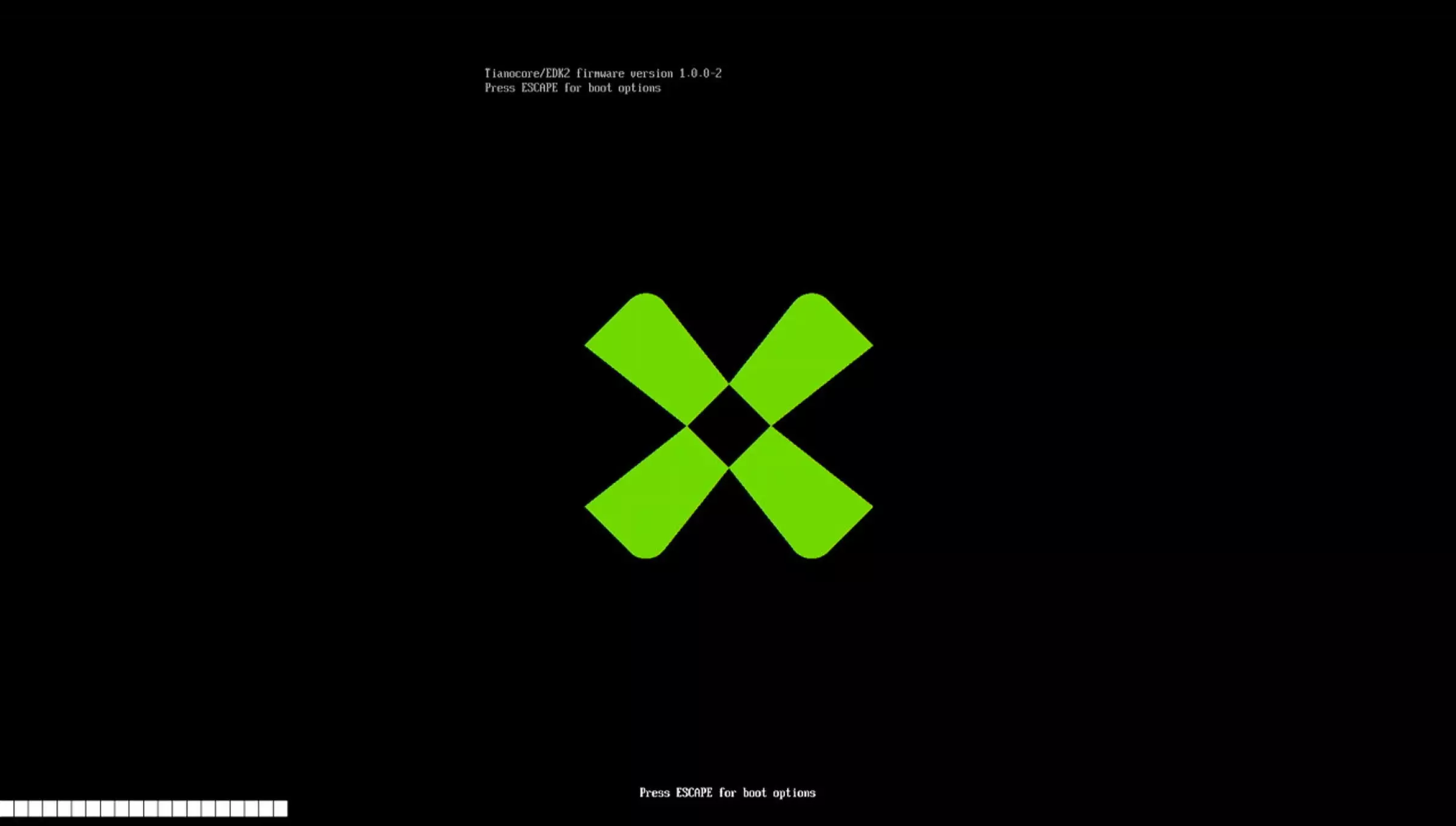
Tianocore/EDK2 firmware version 1.0.0-2
Press ESCAPE for boot options
BIOS screen
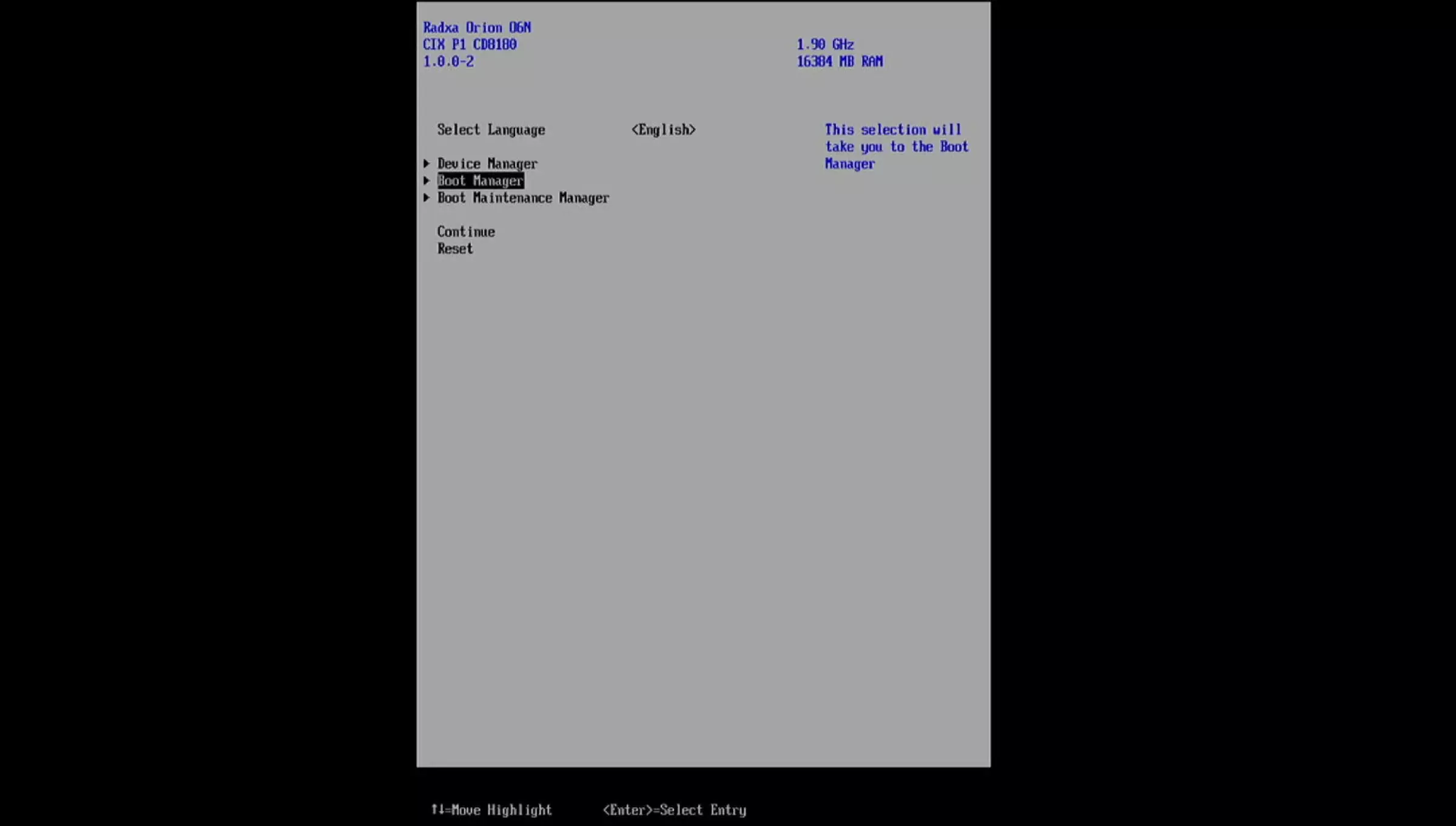
Update the BIOS firmware
On the BIOS screen, select Boot Manager -> UEFI Shell.
Boot Manager screen
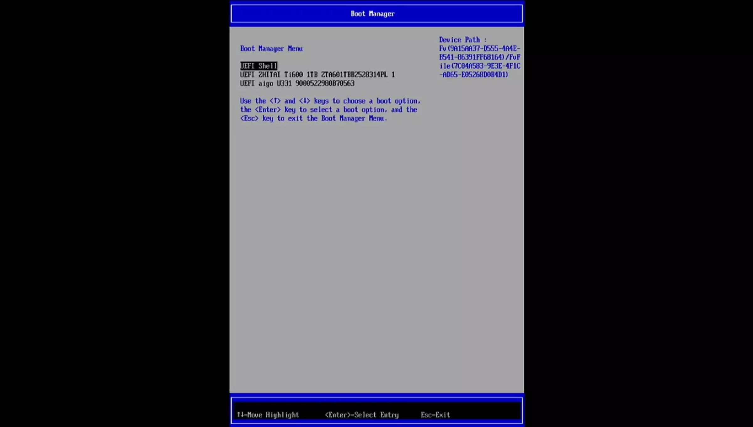
After entering the UEFI Shell, press ESC to cancel auto-update, then manually switch to the target drive to update the BIOS firmware.
UEFI Shell screen

When updating the BIOS firmware, ensure stable power throughout the process. A power loss may cause the update to fail and the board may no longer boot.
- Enter the BIOS directory
The mapping table in the UEFI Shell shows the detected drives. You can use the ls command to list files on each drive to identify which one is the BIOS update USB drive.
As shown, the BIOS update USB drive is FS2, so enter FS2: to switch to that drive.
If only one drive is connected, the BIOS update USB drive will usually be FS0.
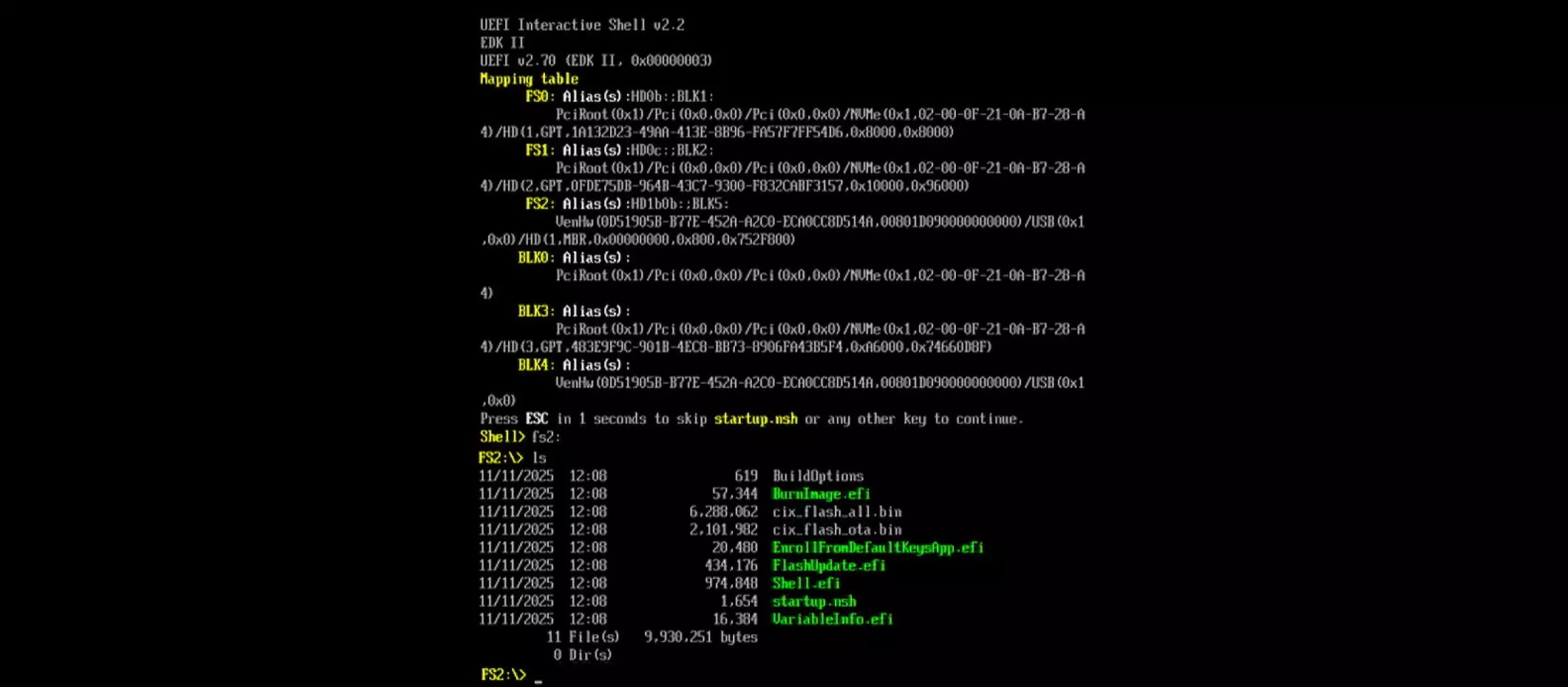
- Update the BIOS firmware
Run startup.nsh and press Enter to update the BIOS firmware.
startup.nsh
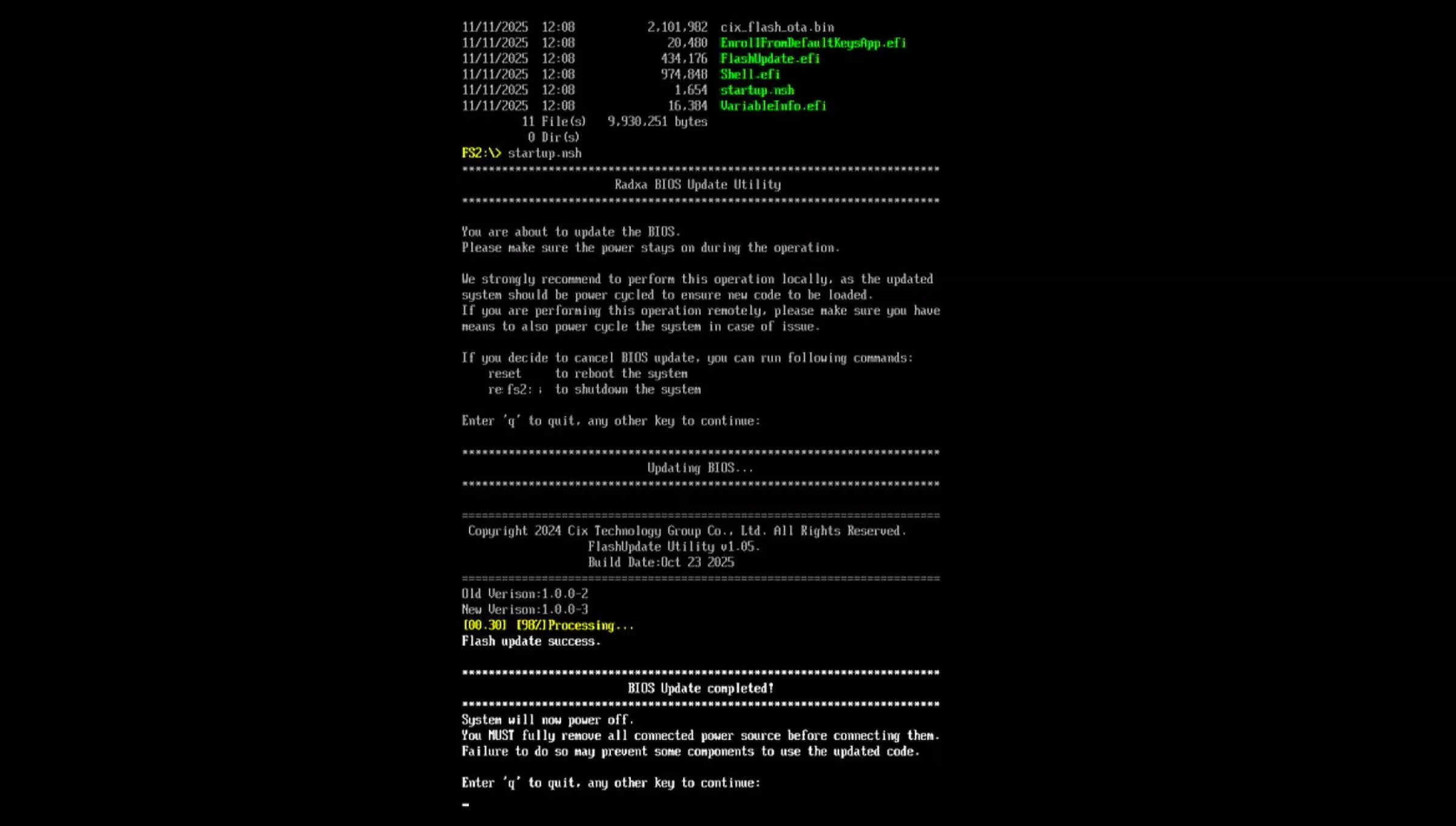
- Reboot the system
After the update completes, unplug and reconnect the power adapter to reboot the system.
Flash BIOS Firmware Using a Programmer (Only When System Cannot Boot)
For users whose BIOS is corrupted and the device cannot boot, or for advanced users who need direct access to the SPI NOR Flash, you can use a CH347T programmer to write the complete BIOS firmware directly to the BIOS chip.
Prerequisites
- Prepare the hardware
- CH347T programmer
- 1.8 V output or 1.8 V level shifter
- SOP8 208mil programming pins (Orion O6N) / SOP8 208mil chip socket (Orion O6)
- Ubuntu system
- Set up the environment
Install the following packages on Ubuntu:
sudo apt update
sudo apt install -y git gcc meson ninja-build pkg-config libusb-1.0-0-dev

git clone https://review.coreboot.org/flashrom
cd flashrom

meson setup build -Dprogrammer=ch347_spi
meson compile -C build
- Download the firmware
Visit the Downloads page to download the latest BIOS firmware.
Flash Mode
Switch the programmer's voltage to 1.8V and enable the programmer's flash mode.
The BIOS chip operates at 1.8 V. Make sure the CH347T output is set to 1.8 V before connecting; using 3.3 V may permanently damage the Flash chip.
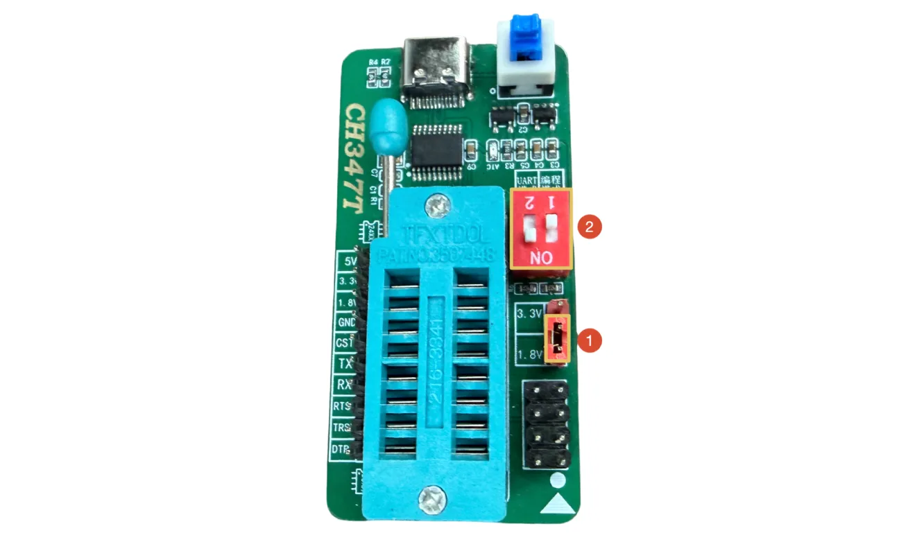
Hardware Connection
- Orion O6
- Orion O6N
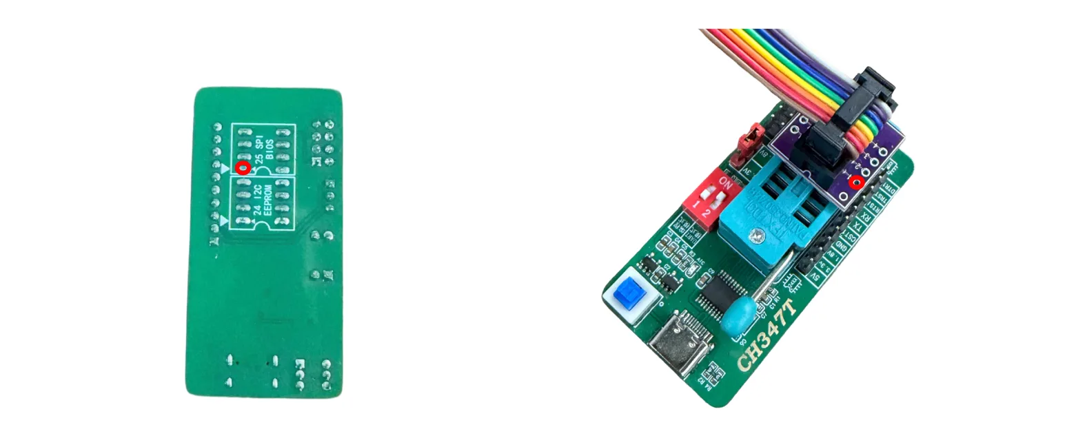
Install the SOP8 208mil chip socket onto the CH347T programmer, place the BIOS chip into the SOP8 208mil chip socket, and make sure pin 1 of the BIOS chip is aligned with pin 1 on the CH347T programmer.
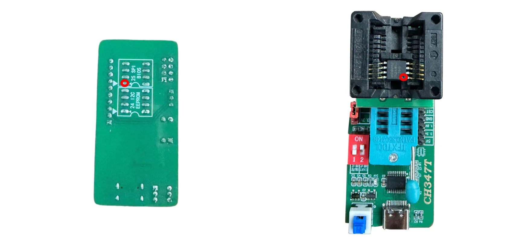
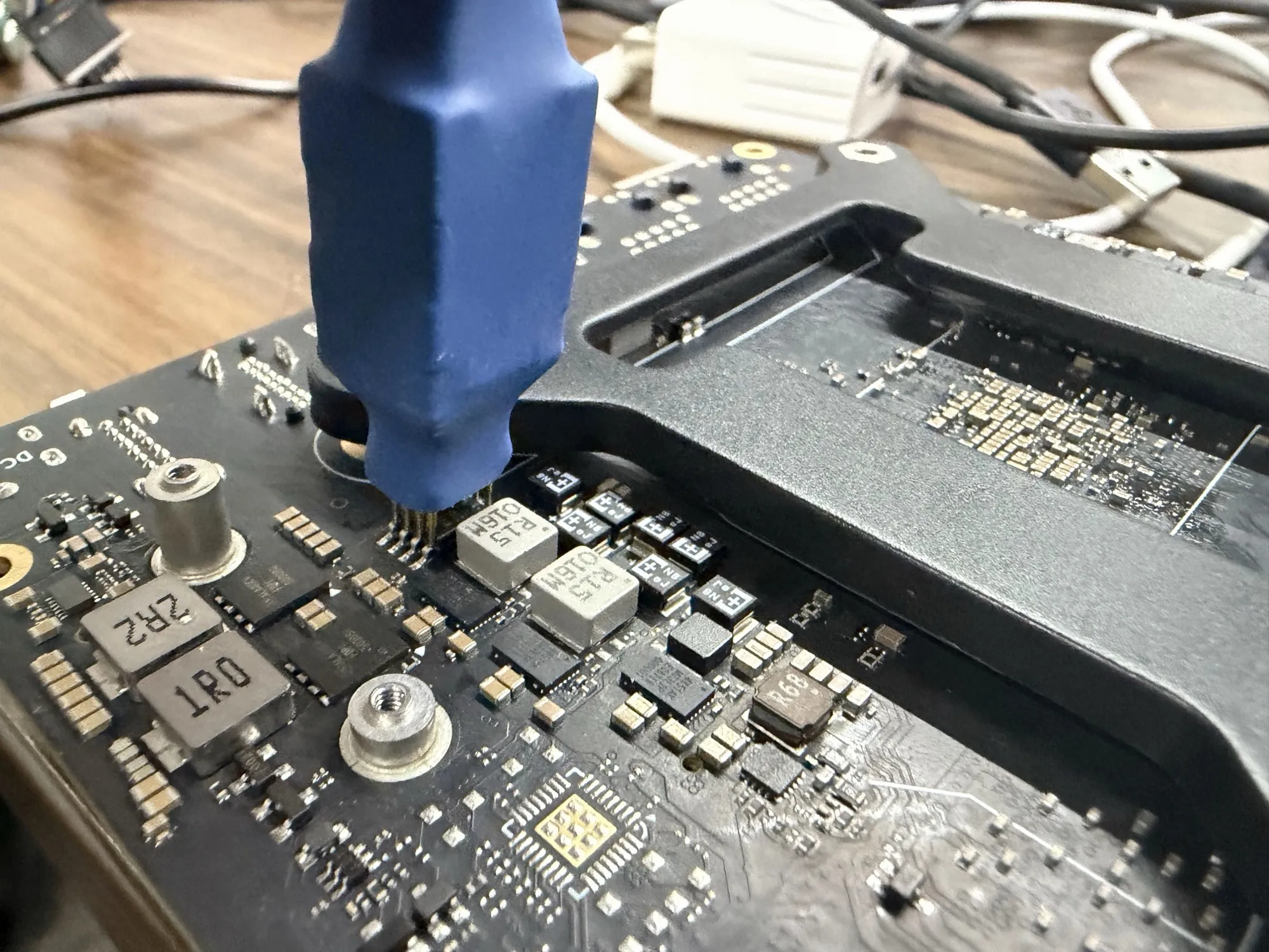
Connect the SOP8 208mil programming pins to the CH347T programmer and the BIOS chip. Align pin 1 of the SOP8 208mil programming pins with pin 1 of the CH347T programmer, then align pin 1 of the programming pins tip with pin 1 of the BIOS chip and press gently to ensure firm contact.
Programmers and programming pins usually mark pin 1 with a circle or triangle, and the board marks pin 1 of the BIOS chip with a triangle.
Verify the Hardware
Connect the programmer to the PC with a USB cable, enter the flashrom folder, and use the following command to check whether the system correctly detects the BIOS chip:
sudo ./build/flashrom -p ch347_spi
If the chip is detected correctly, the terminal will output information similar to the following:
flashrom v1.8.0-rc2 (git:v1.8.0-rc2) on Linux 7.0.0-28-generic (x86_64)
flashrom is free software, get the source code at https://flashrom.org

CH347 SPI clock set to 15MHz.
Found Winbond flash chip "W25Q64.W" (8192 kB, SPI) on ch347_spi.
No operations were specified.
Flash the BIOS Firmware
Place the downloaded BIOS firmware in the flashrom folder, then use the following command to flash the BIOS firmware:
sudo ./build/flashrom -p ch347_spi:spispeed=15M -w cix_flash_all.bin
After the flashing succeeds, the terminal will output information similar to the following:
flashrom v1.8.0-rc2 (git:v1.8.0-rc2) on Linux 7.0.0-28-generic (x86_64)
flashrom is free software, get the source code at https://flashrom.org

CH347 SPI clock set to 15MHz.
Found Winbond flash chip "W25Q64.W" (8192 kB, SPI) on ch347_spi.
Reading old flash chip contents... done.
Updating flash chip contents... Erase/write done from 0 to 7fffff
Verifying flash... VERIFIED.
Remove and Install the SPI Flash Chip
Remove the SPI Flash Chip
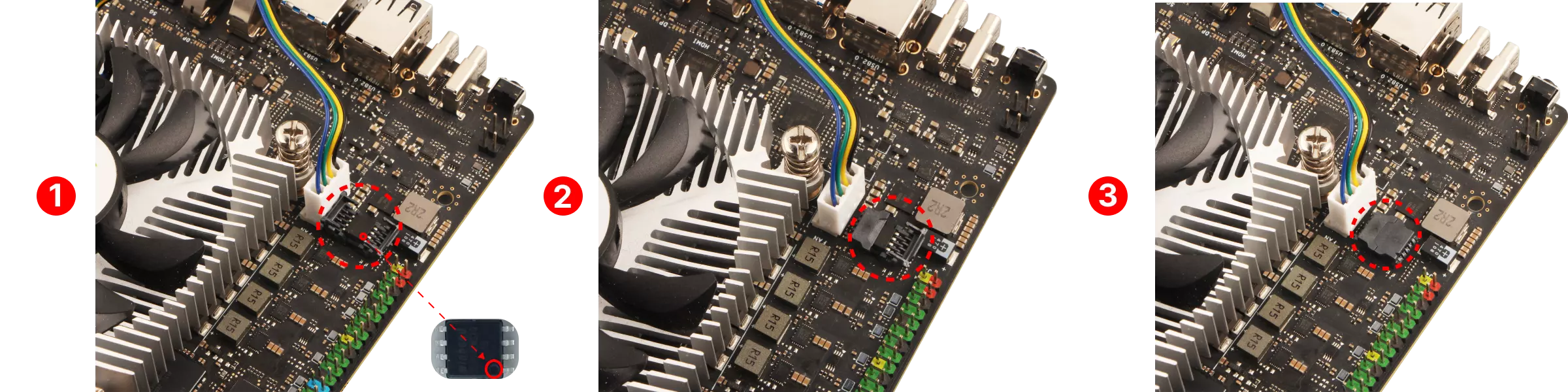
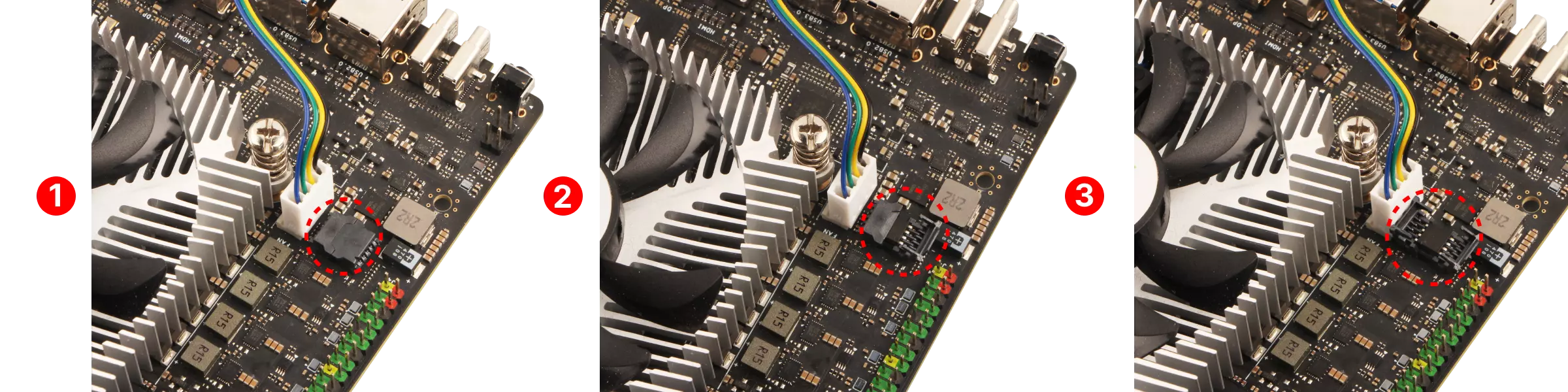
Steps to remove the SPI Flash chip:
① : Locate the SPI Flash chip on the motherboard
② : Open the right latch cover of the SPI Flash
③ : Open the left latch cover of the SPI Flash
After completing the above steps, use tweezers to remove the SPI Flash chip from the motherboard
Install the SPI Flash Chip
① : Install the SPI Flash chip onto the motherboard
② : Reattach the left latch cover of the SPI Flash
③ : Reattach the right latch cover of the SPI Flash
- The circle on the chip corresponds to pin 1, which is marked with a small red circle in the image.
- The socket for the SPI Flash has a triangular arrow that corresponds to pin 1 of the SPI Flash
You can confirm the installation orientation and position of the SPI Flash using the above two methods.