Hardware Information
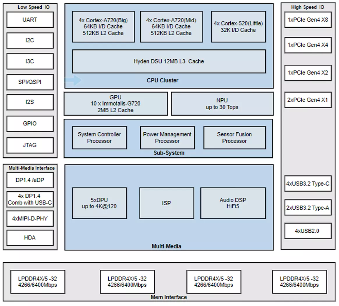
Chip Block Diagram
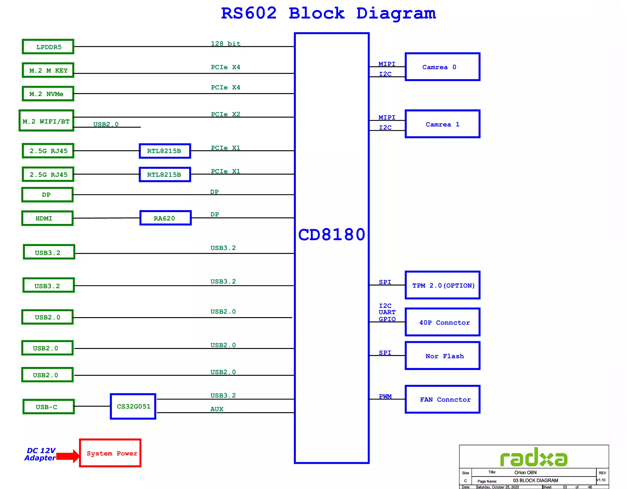
System Block Diagram
Interface Description
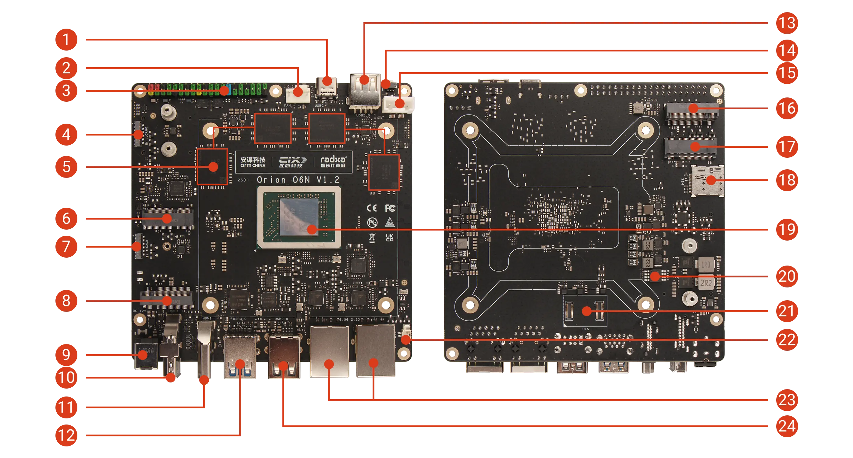
| No. | Description | No. | Description | No. | Description |
|---|---|---|---|---|---|
| 1 | USB Type-C Port (Supports DP Video Output not supporting power delivery) | 9 | 12V DC Power Input (5525) | 17 | M.2 B Key 3042 Slot |
| 2 | 4-Pin Fan Header (PWM Speed Control & Tachometer) | 10 | Standard DP Port | 18 | Nano SIM Card Slot |
| 3 | 40-Pin GPIO Header | 11 | Standard HDMI Port | 19 | CIX P1 SoC |
| 4 | MIPI CSI Interface (4-lane) | 12 | 2x USB 3.0 Type-A | 20 | SPI Nor Flash (BIOS) |
| 5 | LPDDR5 | 13 | USB 2.0 Type-A | 21 | UFS Module Interface |
| 6 | M.2 E Key 2230 Slot | 14 | Power Button | 22 | RTC Battery Connector |
| 7 | MIPI CSI Interface (4-lane) | 15 | 5V / 12V Power Port | 23 | 2x 2.5G Ethernet |
| 8 | M.2 M Key 2280 Slot | 16 | M.2 M Key 2280 Slot | 24 | 2x USB 2.0 Type-A |
Power Interface
Onboard 12V DC power interface (5525 plug) and 5V / 12V power port provide stable power supply to the motherboard.
- 12V DC Power Interface (Recommended): Supports external 12V DC power input
- 5V / 12V Power Port: Supports powering the motherboard through 12V and GND pins. The 5V pin supports power output only, not input.
Power Button
Mainly used to control the power switch of the motherboard.
- When the motherboard is powered off, press the power button to start the motherboard
- When the motherboard is running, a short press of the power button will trigger a power event, which may display the power menu or put the system into suspend mode, depending on the operating system settings
- Press and hold the power button for 4 seconds to force shutdown
USB Type-C Port
Onboard 1x USB Type-C port supporting DP video output, with maximum transfer speed up to 10Gbps.
USB Type-A Ports
Onboard 3x USB 2.0 Type-A ports and 2x USB 3.2 Type-A ports.
- USB 2.0 Type-A: Maximum transfer rate 480Mbps, all USB 2.0 ports share 1.4A total current
- USB 3.2 Type-A: Maximum transfer rate 10Gbps, each port current limited to 1A
HDMI Port
Onboard HDMI Type-A port, supporting up to 4K@60Hz, does not support HDMI CEC function.
DisplayPort
Onboard DP port, supporting up to 4K@120Hz, with Multi-Stream Transport (MST) support.
2.5G Ethernet Ports
Onboard dual 2.5G RJ45 Ethernet ports, supporting 10/100/1000/2500 Mbps auto-negotiation.
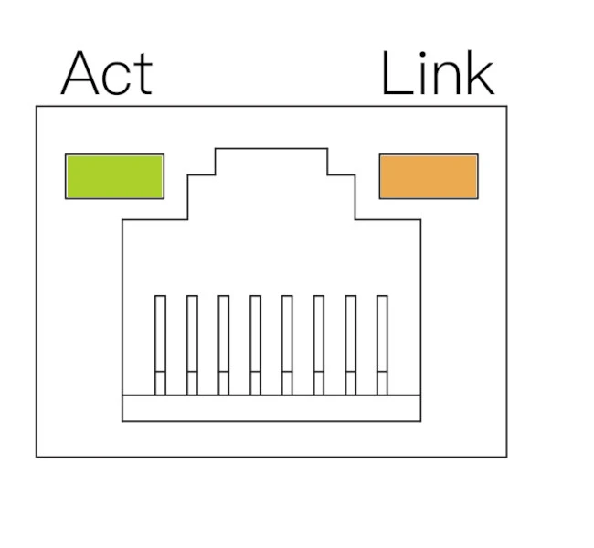
| LED | Status | Description |
|---|---|---|
| Orange | Solid | Link established (device connected to network) |
| Green | Blinking | Data transmission in progress (network activity) |
| Off | - | No link detected (cable unplugged or network issue) |
Fan Interface
Onboard standard ATX 4-Pin fan header, supporting PWM control and tachometer.
Note: The motherboard has silk-screen labels for easy identification and connection.
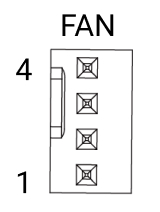
| Pin | Name | Description | Pin | Name | Description | Pin | Name | Description |
|---|---|---|---|---|---|---|---|---|
| 1 | GND | Ground connection | 2 | VCC12V | Power (12V) | 3 | TACH | Tachometer signal (fan speed feedback) |
| 4 | PWM | PWM control signal (3.3V) |
40-Pin GPIO Header
Onboard 40-Pin GPIO (General Purpose Input/Output) interface, providing highly flexible interface support for hardware expansion.
Users can connect various sensors, actuators, communication modules, displays, and other embedded peripherals through the 40-Pin GPIO interface, enabling rapid prototyping and functional verification in fields such as IoT, robotics control, and industrial automation.
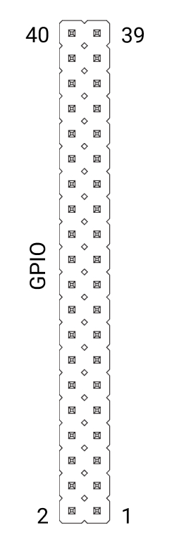
| Function3 | Function2 | Function1 | Pin# | Pin# | Function1 | Function2 |
|---|---|---|---|---|---|---|
| 3.3V | 1 | 2 | 5V | |||
| I2C4_SDA | GPIO062 | 3 | 4 | 5V | ||
| I2C4_SCL | GPIO061 | 5 | 6 | GND | ||
| GPIO071 | 7 | 8 | GPIO103 | UART2_TX | ||
| GND | 9 | 10 | GPIO104 | UART2_RX | ||
| UART0_TXD | PWM0 | GPIO095 | 11 | 12 | GPIO091 | I2S4_SCLK |
| UART0_RXD | PWM1 | GPIO096 | 13 | 14 | GND | |
| UART3_TXD | GPIO105 | 15 | 16 | GPIO106 | UART3_RXD | |
| 3.3V | 17 | 18 | GPIO044 | |||
| SPI2_MOSI | GPIO141 | 19 | 20 | GND | ||
| SPI2_MISO | GPIO138 | 21 | 22 | GPIO045 | ||
| SPI2_CLK | GPIO142 | 23 | 24 | GPIO139 | SPI2_CS0 | |
| GND | 25 | 26 | GPIO140 | SPI2_CS1 | ||
| I2C2_SDA | GPIO056 | 27 | 28 | GPIO055 | I2C2_SCL | |
| GPIO076 | 29 | 30 | GND | |||
| GPIO078 | 31 | 32 | GPIO046 | |||
| GPIO079 | 33 | 34 | GND | |||
| I2S4_TWS | GPIO092 | 35 | 36 | GPIO090 | I2S4_MCLK | |
| GPIO080 | 37 | 38 | GPIO093 | I2S4_DATA_IN | ||
| GND | 39 | 40 | GPIO094 | I2S4_DATA_OUT |
M.2 M Key Slots
Onboard 2x M.2 M Key slots, supporting PCIe Gen4 x4, compatible with 2280-sized M.2 NVMe SSDs for expanding storage needs.
M.2 E Key Slot
Onboard 1x M.2 E Key slot, supporting PCIe Gen4 x2, compatible with 2230-sized WiFi/Bluetooth modules for wireless connectivity.
M.2 B Key Slot
Onboard 1x M.2 B Key slot, compatible with 3042-sized 4G modules for mobile network connectivity when used with a SIM card.
SIM Card Slot
Onboard 1x nano SIM card slot for 4G network connectivity.
Note: The SIM card detection pin (CD) is connected to GND.
UFS Module Connector
Onboard UFS module connector for connecting UFS storage modules, which can be used to expand system storage or as a boot device.
MIPI CSI Interfaces
Onboard 2x MIPI CSI 4-lane interfaces for connecting camera modules.
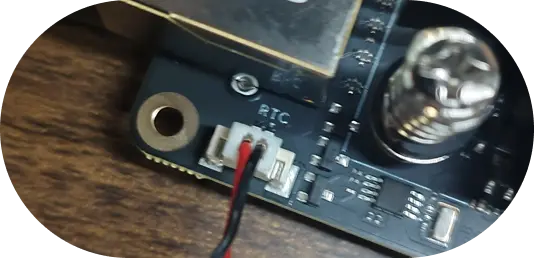
RTC Battery Interface
Onboard 2-Pin 1.25mm RTC interface for connecting a CR2032 coin cell battery.
Note: The silkscreen arrow on the RTC interface points to the negative pole (GND), with VCC connected to 3.3V (red wire represents VCC, black wire represents GND in the diagram).