Hardware Information
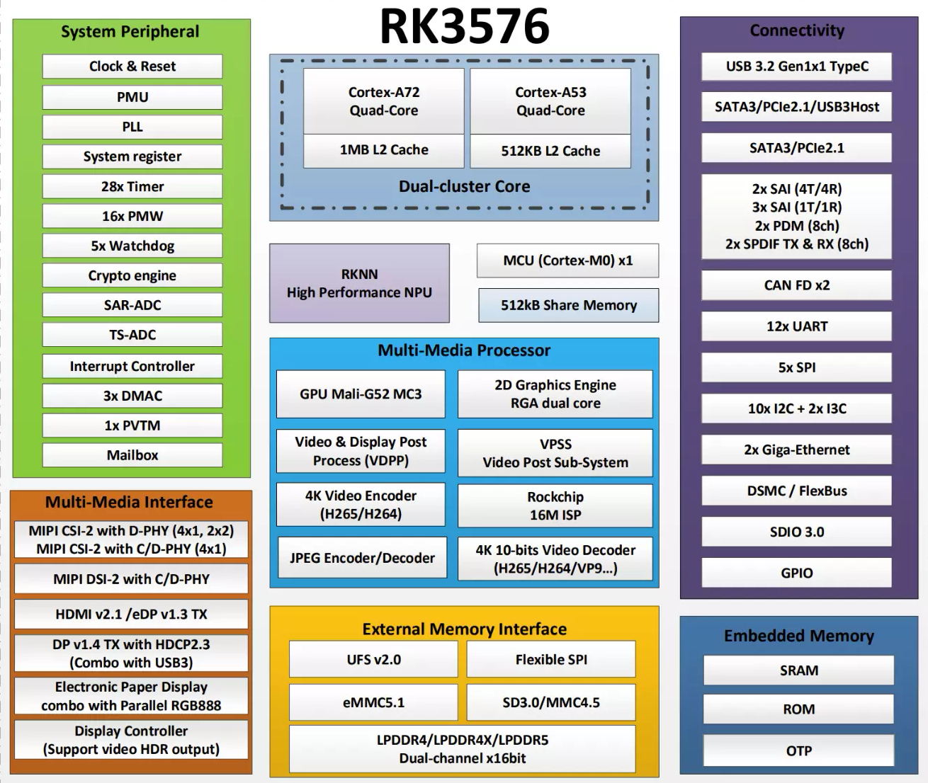
Chip Block Diagram
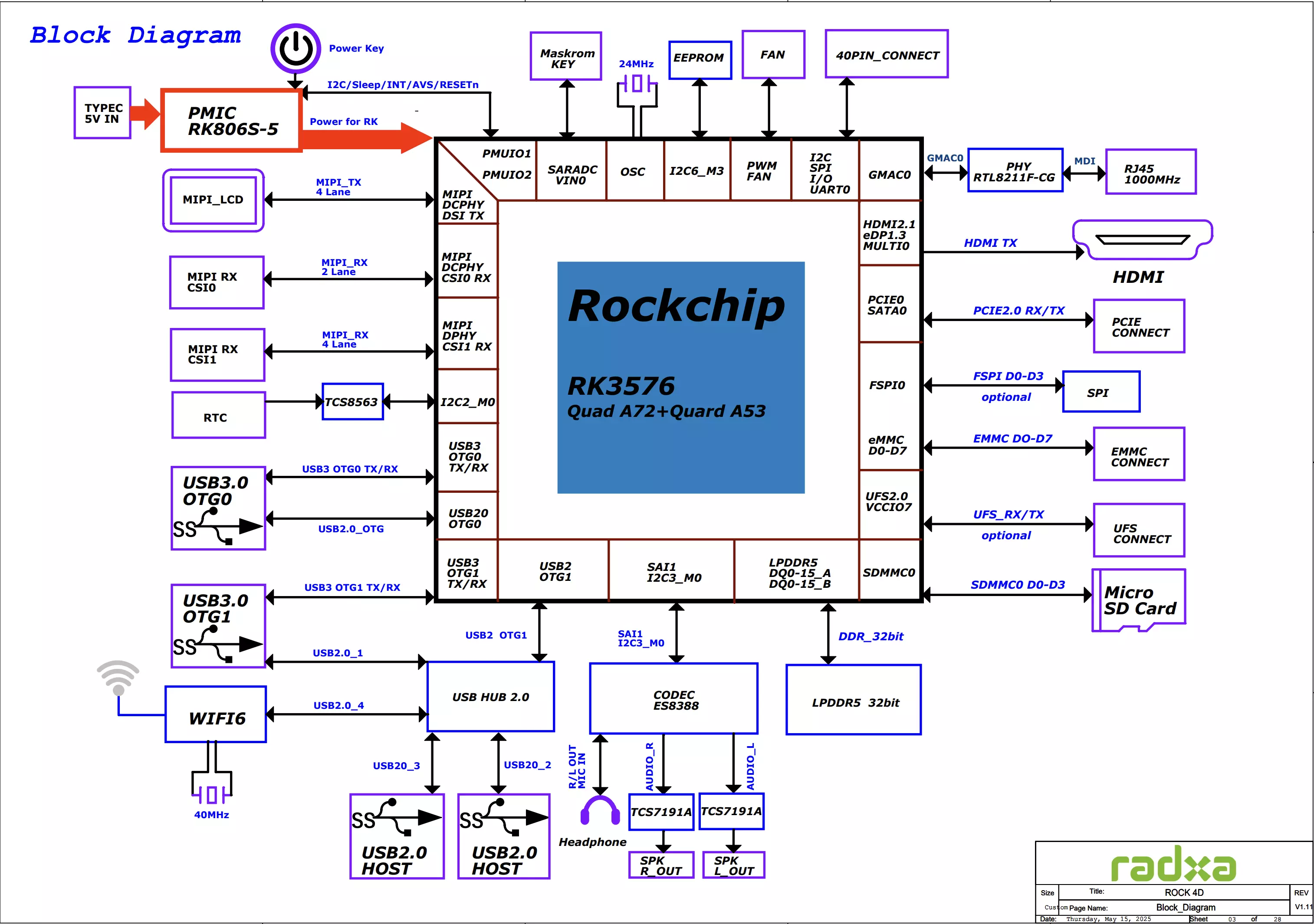
System Block Diagram
Interface Information
For interfaces that support external devices, click on the interface description to view the usage tutorial.
- ROCK 4D
- ROCK 4D v1.12
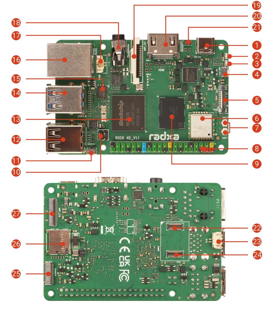
| # | Description | Qty | # | Description | Qty | # | Description | Qty |
|---|---|---|---|---|---|---|---|---|
| ① | USB Type-C Port | 1 | ⑩ | PoE Port | 1 | ⑲ | MIPI CSI Interface | 1 |
| ② | User LED | 1 | ⑪ | Maskrom Button | 1 | ⑳ | HDMI 2.1 Port | 1 |
| ③ | Power LED | 1 | ⑫ | USB 2.0 Type-A Ports | 2 | ㉑ | Recovery Pins | 1 |
| ④ | Power Button | 1 | ⑬ | Rockchip RK3576(J) | 1 | ㉒ | UFS Module Interface | 1 |
| ⑤ | FPC Connector | 1 | ⑭ | USB 3.0 Type-A Ports Up:USB 3.0 Type-A OTG Down:USB 3.0 Type-A HOST | 2 | ㉓ | RTC Interface | 1 |
| ⑥ | WiFi 6 & Bluetooth 5.4 | 1 | ⑮ | SPI NOR Flash | 1 | ㉔ | eMMC Module Interface | 1 |
| ⑦ | Antenna Connector | 1 | ⑯ | Gigabit Ethernet (PoE) | 1 | ㉕ | MIPI CSI Interface | 1 |
| ⑧ | 40-Pin GPIO Header | 1 | ⑰ | Fan Connector | 1 | ㉖ | microSD Card Slot | 1 |
| ⑨ | LPDDR5 RAM | 1 | ⑱ | Headphone Jack | 1 | ㉗ | MIPI DSI Interface | 1 |
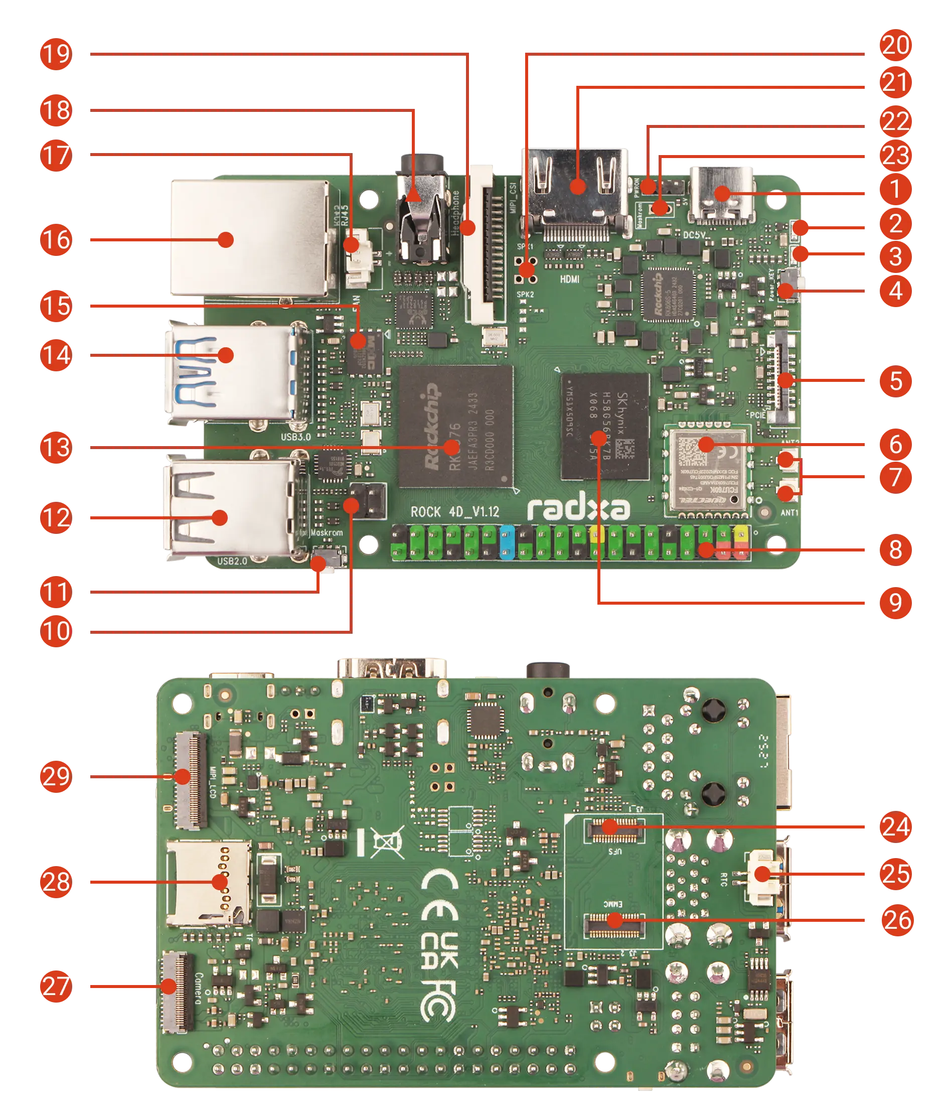
| # | Description | Qty | # | Description | Qty | # | Description | Qty |
|---|---|---|---|---|---|---|---|---|
| ① | USB Type-C Port | 1 | ⑪ | Maskrom Button | 1 | ㉑ | HDMI 2.1 | 1 |
| ② | User LED | 1 | ⑫ | USB 2.0 Type-A Ports | 2 | ㉒ | Power Input Interface | 1 |
| ③ | Power LED | 1 | ⑬ | Rockchip RK3576(J) | 1 | ㉓ | Maskrom Reserved Pads | 1 |
| ④ | Power Button | 1 | ⑭ | USB 3.0 Type-A Ports Up:USB 3.0 Type-A OTG Down:USB 3.0 Type-A HOST | 2 | ㉔ | UFS Module Interface | 1 |
| ⑤ | FPC Connector | 1 | ⑮ | SPI NOR Flash | 1 | ㉕ | RTC Interface | 1 |
| ⑥ | WiFi6 & Bluetooth 5.4 | 1 | ⑯ | Gigabit Ethernet (PoE) | 1 | ㉖ | eMMC Module Interface | 1 |
| ⑦ | Antenna Connector | 1 | ⑰ | Fan Connector | 1 | ㉗ | MIPI CSI Interface | 1 |
| ⑧ | 40 Pin GPIO Header | 1 | ⑱ | Headphone Jack | 1 | ㉘ | microSD Card Slot | 1 |
| ⑨ | LPDDR5 RAM | 1 | ⑲ | MIPI CSI Interface | 1 | ㉙ | MIPI DSI Interface | 1 |
| ⑩ | PoE Port | 1 | ⑳ | Speaker Reserved Pads | 1 |
- User LED
The user LED will blink when the system is booting up normally.
- Power LED
The power LED will light up when the system is powered on and functioning correctly.
- Power Button
Short press to power on or access power menu options; long press to power off.
- LPDDR5 RAM
Available in 2GB / 4GB / 8GB / 16GB capacity options.
- Rockchip RK3576(J)
The Radxa ROCK 4D is available in two SoC versions: Commercial-grade ROCK 4D based on RK3576 and Industrial-grade ROCK 4D based on RK3576J.