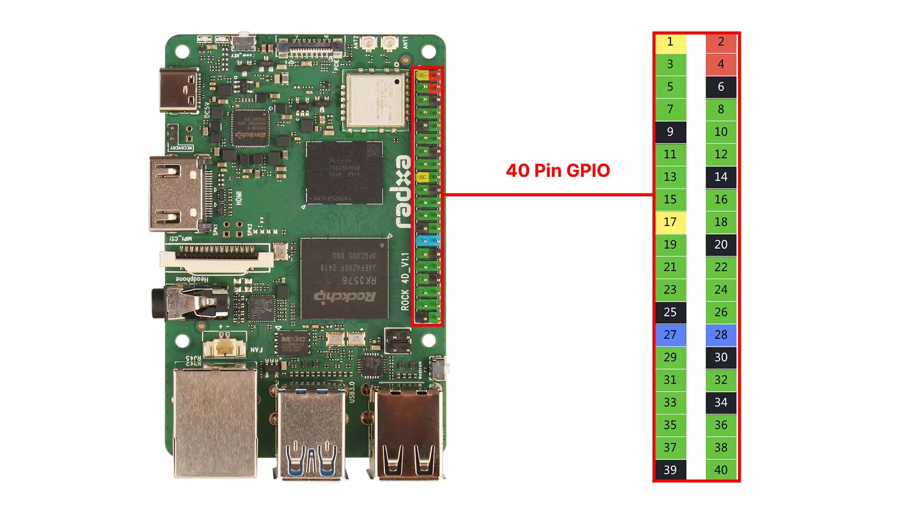
40-Pin GPIO Interface
The Radxa ROCK 4D features an onboard 40-Pin GPIO (General Purpose Input/Output) interface, providing highly flexible interface support for hardware expansion.
Users can connect various sensors, actuators, communication modules, displays, and other embedded peripherals through the 40-Pin GPIO interface, enabling rapid prototyping and functional verification in fields such as IoT, robotics control, and industrial automation.
When using the 40-Pin GPIO interface, please pay attention to the pin connections and peripherals. Ensure correct pin connections as improper operations may cause hardware damage to the device.
GPIO Features
The ROCK 4D supports connecting external devices to its onboard GPIO pins, with support for UART, SPI, I2C, I2S, PWM, CAN, ADC, and more.
| Function7 | Function6 | Function5 | Function4 | Function3 | Function2 | Function1 | Pin# | Pin# | Function1 | Function2 | Function3 | Function4 | Function5 | Function6 | Function7 |
|---|---|---|---|---|---|---|---|---|---|---|---|---|---|---|---|
| 3V3 | 1 | 2 | 5V | ||||||||||||
| PDM0_SDI1_M2 | I2C8_SDA_M1 | UART2_RX_M0 | GPIO1_C7_d | 3 | 4 | 5V | |||||||||
| PDM0_SDI0_M2 | I2C8_SCL_M1 | UART2_TX_M0 | GPIO1_C6_d | 5 | 6 | GND | |||||||||
| SPI2_CSN0_M1 | I2C6_SDA_M1 | UART4_CTSN_M1 | GPIO1_C3_u | 7 | 8 | GPIO0_D4_u | UART0_TX_M0_DEBUG | ||||||||
| GND | 9 | 10 | GPIO0_D5_u | UART0_RX_M0_DEBUG | |||||||||||
| UART2_RTSN_M0 | SPI2_MOSI_M1 | UART4_TX_M1 | GPIO1_C4_d | 11 | 12 | GPIO1_D1_d | UART10_RX_M1 | I3C0_SDA_PU_M1 | SAI2_SCLK_M0 | ||||||
| PWM1_CH0_M2 | GPIO2_C0_d | 13 | 14 | GND | |||||||||||
| UART2_CTSN_M0 | SPI2_MISO_M1 | UART4_RX_M1 | GPIO1_C5_d | 15 | 16 | GPIO2_B6_d | UART7_TX_M0 | I2C8_SCL_M2 | |||||||
| 3V3 | 17 | 18 | GPIO2_B7_d | UART7_RX_M0 | I2C8_SDA_M2 | ||||||||||
| SAI3_LRCK_M1 | PWM1_CH1_M1 | SPI1_MOSI_M0 | I2C9_SCL_M1 | GPIO1_B5_d | 19 | 20 | GND | ||||||||
| SAI3_SDO_M1 | SPI1_MISO_M0 | UART3_CTSN_M2 | GPIO1_B6_d | 21 | 22 | GPIO2_D7_d | PWM2_CH7_M2 | ||||||||
| SAI3_SCLK_M1 | PWM1_CH0_M1 | SPI1_CLK_M0 | I2C9_SDA_M1 | GPIO1_B4_d | 23 | 24 | GPIO1_B7_d | SPI1_CSN0_M0 | SAI3_SDI_M1 | UART3_RTSN_M2 | |||||
| GND | 25 | 26 | GPIO1_C0_d | UART3_TX_M2 | SPI1_CSN1_M0 | PWM0_CH0_M1 | PDM0_SDI2_M2 | ||||||||
| CAN1_RX_M1 | SAI4_SCLK_M2 | PWM2_CH3_M1 | I2C6_SDA_M3 | GPIO4_C7_d | 27 | 28 | GPIO4_C6_d | I2C6_SCL_M3 | PWM2_CH2_M1 | SAI4_SDI_M2 | CAN1_TX_M1 | ||||
| CAN1_TX_M3 | GPIO3_A2_d | 29 | 30 | GND | |||||||||||
| PDM0_CLK0_M2 | SAI3_MCLK_M1 | UART3_RX_M2 | GPIO1_C1_d | 31 | 32 | GPIO1_D5_d | UART10_CTSN_M1 | I2C5_SDA_M1 | SPI2_CLK_M1 | PDM0_CLK1_M2 | |||||
| PWM1_CH2_M1 | SPI2_CSN1_M1 | I2C6_SCL_M1 | UART4_RTSN_M1 | GPIO1_C2_u | 33 | 34 | GND | ||||||||
| SAI2_LRCK_M0 | PWM1_CH3_M1 | I3C0_SCL_M1 | GPIO1_D2_d | 35 | 36 | GPIO1_D4_d | UART10_RTSN_M1 | I2C5_SCL_M1 | SAI2_MCLK_M0 | PDM0_SDI3_M2 | |||||
| CAN1_RX_M3 | GPIO3_A3_d | 37 | 38 | GPIO1_D3_d | I3C0_SDA_M1 | PWM1_CH4_M1 | SAI2_SDI_M0 | ||||||||
| GND | 39 | 40 | GPIO1_D0_d | UART10_TX_M1 | SAI2_SDO_M0 |
GPIO Usage
This section demonstrates common GPIO usage methods through the onboard 40-Pin GPIO interface.
GPIO Input
Hardware Preparation
- Motherboard: Radxa ROCK 4D
- 1x Female-to-Female Jumper Wire
Hardware Connection
To perform GPIO input testing using GPIO_Pin_3, you can connect to the PIN_3 using a female-to-female jumper wire.
Reading Test
Use the gpiofind command to locate the device node corresponding to the GPIO pin, then use the gpioget command to read the pin state.
gpioget $(gpiofind PIN_3)
You can connect the jumper wire from PIN3 to either GND or 3.3V, then read the pin state.
Terminal output example: When I connect the pin to GND, the output is (terminal output 0 indicates the pin is low, 1 indicates high level):
0
GPIO Output
Hardware Preparation
- Motherboard: Radxa ROCK 4D
- 1x Female-to-Female Jumper Wire
Hardware Connection
To perform GPIO output testing using GPIO_Pin_3, you can connect to the PIN_3 using a female-to-female jumper wire.
Output Test
Use the gpiofind command to locate the device node corresponding to the GPIO pin, then use the gpioset command to set the pin state.
# Set output high
gpioset -m signal $(gpiofind PIN_3)=1
# Set output low
gpioset -m signal $(gpiofind PIN_3)=0
-m signal: Set pin to signal mode$(gpiofind PIN_3): Find the device node corresponding to the GPIO pin=1: Set pin state to high level
You can measure the pin voltage with a multimeter to determine the pin state, or connect the pin to other controllable pins to read the pin state.
UART Usage
UART (Universal Asynchronous Receiver/Transmitter) is a widely used serial communication protocol for asynchronous serial data transfer between embedded systems, computers, and peripherals.
Hardware Preparation
- Motherboard: Radxa ROCK 4D
- 1x Female-to-Female Jumper Wire
Hardware Connection
For loopback testing using UART4-M1 pins, we need to short-circuit PIN_11 (UART4_TX_M1) and PIN_15 (UART4_RX_M1) using a female-to-female jumper wire.
For UART loopback testing, we only need to connect the TX and RX pins.
When connecting to other serial modules later, you'll also need to connect the GND pin to ensure a common ground between the communicating devices.
Loopback Test
- Enable UART4-M1
Use the rsetup tool to enable UART4-M1: Overlays --> Manage Overlays --> Check Enable UART4-M1.
After enabling UART4-M1, a system reboot is required for the changes to take effect.
For more information about the rsetup tool, refer to the Rsetup Tool tutorial.
- Set Serial Port Permissions
For UART4-M1, the corresponding device node is /dev/ttyS4. We need to set the serial port permissions to ensure the current user has access to this device node.
sudo chmod 777 /dev/ttyS4
- Configure Serial Port Parameters
Use the following command to set the serial communication parameters:
sudo stty -F /dev/ttyS4 115200 cs8 -parenb -cstopb -echo
115200: Baud ratecs8: 8 data bits-parenb: No parity bit-cstopb: 1 stop bit-echo: Disable echo
- Transmit Data via Serial Port
Open a terminal and enter the following command:
while true; do echo "UART4 test" > /dev/ttyS4; sleep 1; done
- Receive Serial Data
Open another terminal and enter the following command:
cat /dev/ttyS4
If the loopback test is successful, you should see the message UART4 test appear every second in the terminal receiving the serial data.
I2C Usage
I2C is a widely used synchronous serial communication protocol developed by Philips (now NXP), primarily used for short-distance communication between chips.
Hardware Preparation
- Motherboard: Radxa ROCK 4D
- 4x Female-to-Female Jumper Wires
- OLED Display (I2C Communication)
Hardware Connection
Connect the ROCK 4D to the OLED display using 4 female-to-female jumper wires.
| ROCK 4D | OLED Display |
|---|---|
| PIN_1 (3.3V) | VCC |
| PIN_3 (I2C8_SDA_M1) | SDA |
| PIN_5 (I2C8_SCL_M1) | SCL |
| PIN_9 (GND) | GND |
I2C Testing
- Enable I2C8-M1
Use the rsetup tool to enable I2C8-M1: Overlays --> Manage Overlays --> Check Enable I2C8-M1.
After enabling I2C8-M1, a system reboot is required for the changes to take effect.
- Query I2C Bus Devices
Use the i2cdetect command to query information about I2C bus devices.
- Install Dependencies
Open a terminal and enter the following commands to install Python3-periphery and i2c-tools:
sudo apt update
sudo apt install python3-periphery i2c-tools
- View I2C Buses
Use the i2cdetect command to view all I2C buses on the device.
sudo i2cdetect -l
Terminal output will be similar to:
i2c-1   i2c             rk3x-i2c                                I2C adapter
i2c-2   i2c             rk3x-i2c                                I2C adapter
i2c-3   i2c             rk3x-i2c                                I2C adapter
i2c-6   i2c             rk3x-i2c                                I2C adapter
i2c-8   i2c             rk3x-i2c                                I2C adapter
i2c-10  i2c             ddc                                     I2C adapter
- View I2C Bus Devices
Use the i2cdetect command to view devices mounted on a specific I2C bus. Replace * with a number, for example, use 8 to view devices on i2c-8.
sudo i2cdetect -y -r *
# Example
sudo i2cdetect -y -r 8
Example terminal output (the OLED display has I2C address 0x3c):
     0  1  2  3  4  5  6  7  8  9  a  b  c  d  e  f
00:                         -- -- -- -- -- -- -- --
10: -- -- -- -- -- -- -- -- -- -- -- -- -- -- -- --
20: -- -- -- -- -- -- -- -- -- -- -- -- -- -- -- --
30: -- -- -- -- -- -- -- -- -- -- -- -- 3c -- -- --
40: -- -- -- -- -- -- -- -- -- -- -- -- -- -- -- --
50: -- -- -- -- -- -- -- -- -- -- -- -- -- -- -- --
60: -- -- -- -- -- -- -- -- -- -- -- -- -- -- -- --
70: -- -- -- -- -- -- -- --
- I2C Communication Test
- Python Script
Create a new Python script named oled_test.py with the following content. Note that I2C_ADDR is the I2C address of the OLED display, and I2C_BUS is the I2C bus where the OLED is mounted. Modify these values according to your setup.
from periphery import I2C
import time

I2C_ADDR = 0x3c
I2C_BUS = "/dev/i2c-8"

i2c = I2C(I2C_BUS)

init_cmds = [
0xAE, # Display off
0x00, # Set lower column address
0x10, # Set higher column address
0x40, # Set display start line
0xB0, # Set page address
0x81, # Set contrast control
0xCF,
0xA1, # Set segment remap
0xA6, # Normal display
0xA8, # Set multiplex ratio
0x3F,
0xC8, # Set COM output scan direction
0xD3, # Set display offset
0x00,
0xD5, # Set display clock divide ratio/oscillator frequency
0x80,
0xD9, # Set pre-charge period
0xF1,
0xDA, # Set COM pins hardware configuration
0x12,
0xDB, # Set VCOMH deselect level
0x40,
0x8D, # Enable charge pump regulator
0x14,
0xAF # Display on
]

for cmd in init_cmds:
i2c.transfer(I2C_ADDR, [I2C.Message([0x00, cmd])])

def oled*clear():
for page in range(8):
i2c.transfer(I2C_ADDR, [I2C.Message([0x00, 0xB0 + page])])
i2c.transfer(I2C_ADDR, [I2C.Message([0x00, 0x00])])
i2c.transfer(I2C_ADDR, [I2C.Message([0x00, 0x10])])
for * in range(128):
i2c.transfer(I2C_ADDR, [I2C.Message([0x40, 0x00])])

char_map = {
"H": [0x00, 0x7F, 0x08, 0x08, 0x08, 0x7F,],
"R": [0x00, 0x7F, 0x09, 0x19, 0x29, 0x46],
"e": [0x00, 0x38, 0x54, 0x54, 0x54, 0x18],
"l": [0x00, 0x00, 0x41, 0x7F, 0x40, 0x00],
"o": [0x00, 0x38, 0x44, 0x44, 0x44, 0x38],
"r": [0x00, 0x7C, 0x08, 0x04, 0x04, 0x08],
"a": [0x00, 0x20, 0x54, 0x54, 0x54, 0x78],
"d": [0x00, 0x38, 0x44, 0x44, 0x48, 0x7F],
"x": [0x00, 0x44, 0x28, 0x10, 0x28, 0x44]
}

def string_to_bytes(string):
bytes_list = []
for char in string:
bytes_list.extend(char_map.get(char, [0x00] \* 4))
bytes_list.append(0x00)
return bytes_list

oled_clear()
hello_world_bytes = string_to_bytes("Hello Radxa")
i2c.transfer(I2C_ADDR, [I2C.Message([0x00, 0xB0])])
i2c.transfer(I2C_ADDR, [I2C.Message([0x00, 0x00])])
i2c.transfer(I2C_ADDR, [I2C.Message([0x00, 0x10])])
for byte in hello_world_bytes:
i2c.transfer(I2C_ADDR, [I2C.Message([0x40, byte])])

i2c.close()
- Run the Script
Open a terminal and enter the following command to run the script:
python3 oled_test.py
If everything works correctly, you should see the output Hello Radxa on the OLED display.
SPI Usage
SPI (Serial Peripheral Interface) is a high-speed, full-duplex, synchronous serial communication protocol developed by Motorola (now NXP). It is primarily used for short-distance chip-to-chip communication, commonly found in data transfer between microcontrollers and devices such as sensors, memory (e.g., Flash), and displays.
Hardware Preparation
- Motherboard: Radxa ROCK 4D
- 1x Female-to-Female Jumper Wire
Hardware Connection
For loopback testing using the SPI1-M0 pins, connect PIN_19 (SPI1_MOSI_M0) and PIN_21 (SPI1_MISO_M0) using a female-to-female jumper wire.
Since we're testing SPI functionality in loopback mode, we only need to connect the MOSI and MISO pins.
If you connect other SPI modules later, you'll also need to connect at least the GND pin to ensure a common ground for communication.
Loopback Test
- Enable SPI1-M0
Use the rsetup tool to enable SPI1-M0: Overlays --> Manage Overlays --> Check Enable spidev on SPI1-M0 over CS0.
After enabling SPI1-M0, a system reboot is required for the changes to take effect.
- Query SPI Bus Devices
Use the ls /dev/spidev* command to query information about SPI bus devices.
ls /dev/spidev\*
Terminal output will be similar to:
/dev/spidev1.0
- SPI Communication Test
- C Code
Create a new C file named spidev_test.c with the following content. Note that static const char *device = "/dev/spidev1.0"; is the SPI bus device node. Modify this according to your actual setup.
/\*

- SPI testing utility (using spidev driver)
-
- Copyright (c) 2007 MontaVista Software, Inc.
- Copyright (c) 2007 Anton Vorontsov <[email protected]>
-
- This program is free software; you can redistribute it and/or modify
- it under the terms of the GNU General Public License as published by
- the Free Software Foundation; either version 2 of the License.
-
- Cross-compile with cross-gcc -I/path/to/cross-kernel/include
  \*/

#include <stdint.h>
#include <unistd.h>
#include <stdio.h>
#include <stdlib.h>
#include <string.h>
#include <getopt.h>
#include <fcntl.h>
#include <sys/ioctl.h>
#include <linux/ioctl.h>
#include <sys/stat.h>
#include <linux/types.h>
#include <linux/spi/spidev.h>

#define ARRAY_SIZE(a) (sizeof(a) / sizeof((a)[0]))

static void pabort(const char \*s)
{
perror(s);
abort();
}

static const char *device = "/dev/spidev1.0";
static uint32_t mode;
static uint8_t bits = 8;
static char *input_file;
static char \*output_file;
static uint32_t speed = 500000;
static uint16_t delay;
static int verbose;

uint8_t default_tx[] = {
0xFF, 0xFF, 0xFF, 0xFF, 0xFF, 0xFF,
0x40, 0x00, 0x00, 0x00, 0x00, 0x95,
0xFF, 0xFF, 0xFF, 0xFF, 0xFF, 0xFF,
0xFF, 0xFF, 0xFF, 0xFF, 0xFF, 0xFF,
0xFF, 0xFF, 0xFF, 0xFF, 0xFF, 0xFF,
0xF0, 0x0D,
};

uint8_t default_rx[ARRAY_SIZE(default_tx)] = {0, };
char \*input_tx;

static void hex_dump(const void *src, size_t length, size_t line_size,
char *prefix)
{
int i = 0;
const unsigned char *address = src;
const unsigned char *line = address;
unsigned char c;

    printf("%s | ", prefix);
    while (length-- > 0) {
        printf("%02X ", *address++);
        if (!(++i % line_size) || (length == 0 && i % line_size)) {
            if (length == 0) {
                while (i++ % line_size)
                    printf("__ ");
            }
            printf(" | ");  /* right close */
            while (line < address) {
                c = *line++;
                printf("%c", (c < 33 || c == 255) ? 0x2E : c);
            }
            printf("\n");
            if (length > 0)
                printf("%s | ", prefix);
        }
    }

}

/\*

- Unescape - process hexadecimal escape character
- converts shell input "\x23" -> 0x23
  _/
  static int unescape(char _\_dst, char *\_src)
  {
  int ret = 0;
  int match;
  char *src = \_src;
  char \*dst = \_dst;
  unsigned int ch;

      while (*src) {
          if (*src == '\\' && *(src+1) == 'x') {
              match = sscanf(src + 2, "%2x", &ch);
              if (!match)
                  pabort("malformed input string");

              src += 4;
              *dst++ = (unsigned char)ch;
          } else {
              *dst++ = *src++;
          }
          ret++;
      }
      return ret;

  }

static void transfer(int fd, uint8_t const *tx, uint8_t const *rx, size_t len)
{
int ret;
int out_fd;
struct spi_ioc_transfer tr = {
.tx_buf = (unsigned long)tx,
.rx_buf = (unsigned long)rx,
.len = len,
.delay_usecs = delay,
.speed_hz = speed,
.bits_per_word = bits,
};

    if (mode & SPI_TX_QUAD)
        tr.tx_nbits = 4;
    else if (mode & SPI_TX_DUAL)
        tr.tx_nbits = 2;
    if (mode & SPI_RX_QUAD)
        tr.rx_nbits = 4;
    else if (mode & SPI_RX_DUAL)
        tr.rx_nbits = 2;
    if (!(mode & SPI_LOOP)) {
        if (mode & (SPI_TX_QUAD | SPI_TX_DUAL))
            tr.rx_buf = 0;
        else if (mode & (SPI_RX_QUAD | SPI_RX_DUAL))
            tr.tx_buf = 0;
    }

    ret = ioctl(fd, SPI_IOC_MESSAGE(1), &tr);
    if (ret < 1)
        pabort("can't send spi message");

    if (verbose)
        hex_dump(tx, len, 32, "TX");

    if (output_file) {
        out_fd = open(output_file, O_WRONLY | O_CREAT | O_TRUNC, 0666);
        if (out_fd < 0)
            pabort("could not open output file");

        ret = write(out_fd, rx, len);
        if (ret != len)
            pabort("not all bytes written to output file");

        close(out_fd);
    }

    if (verbose || !output_file)
        hex_dump(rx, len, 32, "RX");

}

static void print_usage(const char \*prog)
{
printf("Usage: %s [-DsbdlHOLC3]\n", prog);
puts(" -D --device device to use (default /dev/spidev0.0)\n"
" -s --speed max speed (Hz)\n"
" -d --delay delay (usec)\n"
" -b --bpw bits per word\n"
" -i --input input data from a file (e.g. \"test.bin\")\n"
" -o --output output data to a file (e.g. \"results.bin\")\n"
" -l --loop loopback\n"
" -H --cpha clock phase\n"
" -O --cpol clock polarity\n"
" -L --lsb least significant bit first\n"
" -C --cs-high chip select active high\n"
" -3 --3wire SI/SO signals shared\n"
" -v --verbose Verbose (show tx buffer)\n"
" -p Send data (e.g. \"1234\\xde\\xad\")\n"
" -N --no-cs no chip select\n"
" -R --ready slave pulls low to pause\n"
" -2 --dual dual transfer\n"
" -4 --quad quad transfer\n");
exit(1);
}

static void parse_opts(int argc, char \*argv[])
{
while (1) {
static const struct option lopts[] = {
{ "device", 1, 0, 'D' },
{ "speed", 1, 0, 's' },
{ "delay", 1, 0, 'd' },
{ "bpw", 1, 0, 'b' },
{ "input", 1, 0, 'i' },
{ "output", 1, 0, 'o' },
{ "loop", 0, 0, 'l' },
{ "cpha", 0, 0, 'H' },
{ "cpol", 0, 0, 'O' },
{ "lsb", 0, 0, 'L' },
{ "cs-high", 0, 0, 'C' },
{ "3wire", 0, 0, '3' },
{ "no-cs", 0, 0, 'N' },
{ "ready", 0, 0, 'R' },
{ "dual", 0, 0, '2' },
{ "verbose", 0, 0, 'v' },
{ "quad", 0, 0, '4' },
{ NULL, 0, 0, 0 },
};
int c;

        c = getopt_long(argc, argv, "D:s:d:b:i:o:lHOLC3NR24p:v",
                lopts, NULL);

        if (c == -1)
            break;

        switch (c) {
        case 'D':
            device = optarg;
            break;
        case 's':
            speed = atoi(optarg);
            break;
        case 'd':
            delay = atoi(optarg);
            break;
        case 'b':
            bits = atoi(optarg);
            break;
        case 'i':
            input_file = optarg;
            break;
        case 'o':
            output_file = optarg;
            break;
        case 'l':
            mode |= SPI_LOOP;
            break;
        case 'H':
            mode |= SPI_CPHA;
            break;
        case 'O':
            mode |= SPI_CPOL;
            break;
        case 'L':
            mode |= SPI_LSB_FIRST;
            break;
        case 'C':
            mode |= SPI_CS_HIGH;
            break;
        case '3':
            mode |= SPI_3WIRE;
            break;
        case 'N':
            mode |= SPI_NO_CS;
            break;
        case 'v':
            verbose = 1;
            break;
        case 'R':
            mode |= SPI_READY;
            break;
        case 'p':
            input_tx = optarg;
            break;
        case '2':
            mode |= SPI_TX_DUAL;
            break;
        case '4':
            mode |= SPI_TX_QUAD;
            break;
        default:
            print_usage(argv[0]);
            break;
        }
    }
    if (mode & SPI_LOOP) {
        if (mode & SPI_TX_DUAL)
            mode |= SPI_RX_DUAL;
        if (mode & SPI_TX_QUAD)
            mode |= SPI_RX_QUAD;
    }

}

static void transfer_escaped_string(int fd, char *str)
{
size_t size = strlen(str);
uint8_t *tx;
uint8_t \*rx;

    tx = malloc(size);
    if (!tx)
        pabort("can't allocate tx buffer");

    rx = malloc(size);
    if (!rx)
        pabort("can't allocate rx buffer");

    size = unescape((char *)tx, str);
    transfer(fd, tx, rx, size);
    free(rx);
    free(tx);

}

static void transfer_file(int fd, char *filename)
{
ssize_t bytes;
struct stat sb;
int tx_fd;
uint8_t *tx;
uint8_t \*rx;

    if (stat(filename, &sb) == -1)
        pabort("can't stat input file");

    tx_fd = open(filename, O_RDONLY);
    if (tx_fd < 0)
        pabort("can't open input file");

    tx = malloc(sb.st_size);
    if (!tx)
        pabort("can't allocate tx buffer");

    rx = malloc(sb.st_size);
    if (!rx)
        pabort("can't allocate rx buffer");

    bytes = read(tx_fd, tx, sb.st_size);
    if (bytes != sb.st_size)
        pabort("failed to read input file");

    transfer(fd, tx, rx, sb.st_size);
    free(rx);
    free(tx);
    close(tx_fd);

}

int main(int argc, char \*argv[])
{
int ret = 0;
int fd;

    parse_opts(argc, argv);

    fd = open(device, O_RDWR);
    if (fd < 0)
        pabort("can't open device");

    /*
    * spi mode
    */
    ret = ioctl(fd, SPI_IOC_WR_MODE, &mode);
    if (ret == -1)
        pabort("can't set spi mode");

    ret = ioctl(fd, SPI_IOC_RD_MODE, &mode);
    if (ret == -1)
        pabort("can't get spi mode");

    /*
    * bits per word
    */
    ret = ioctl(fd, SPI_IOC_WR_BITS_PER_WORD, &bits);
    if (ret == -1)
        pabort("can't set bits per word");

    ret = ioctl(fd, SPI_IOC_RD_BITS_PER_WORD, &bits);
    if (ret == -1)
        pabort("can't get bits per word");

    /*
    * max speed hz
    */
    ret = ioctl(fd, SPI_IOC_WR_MAX_SPEED_HZ, &speed);
    if (ret == -1)
        pabort("can't set max speed hz");

    ret = ioctl(fd, SPI_IOC_RD_MAX_SPEED_HZ, &speed);
    if (ret == -1)
        pabort("can't get max speed hz");

    printf("spi mode: 0x%x\n", mode);
    printf("bits per word: %d\n", bits);
    printf("max speed: %d Hz (%d KHz)\n", speed, speed/1000);

    if (input_tx && input_file)
        pabort("only one of -p and --input may be selected");

    if (input_tx)
        transfer_escaped_string(fd, input_tx);
    else if (input_file)
        transfer_file(fd, input_file);
    else
        transfer(fd, default_tx, default_rx, sizeof(default_tx));

    close(fd);

    return ret;

}
- Compilation Tools
Open a terminal and enter the following commands to install the build tools:
sudo apt update
sudo apt install build-essential
- Compile the Code
Open a terminal and enter the following command to compile the code:
gcc -o spidev_test spidev_test.c
- Run the Code
Open a terminal and enter the following command to run the code:
sudo ./spidev_test
If the loopback test is successful, you should see output similar to the following in the terminal:
spi mode: 0x0
bits per word: 8
max speed: 500000 Hz (500 KHz)
RX | FF FF FF FF FF FF 40 00 00 00 00 95 FF FF FF FF FF FF FF FF FF FF FF FF FF FF FF FF FF FF F0 0D | ......@....�..................�.