Hardware interface
This document describes the board's hardware interfaces.
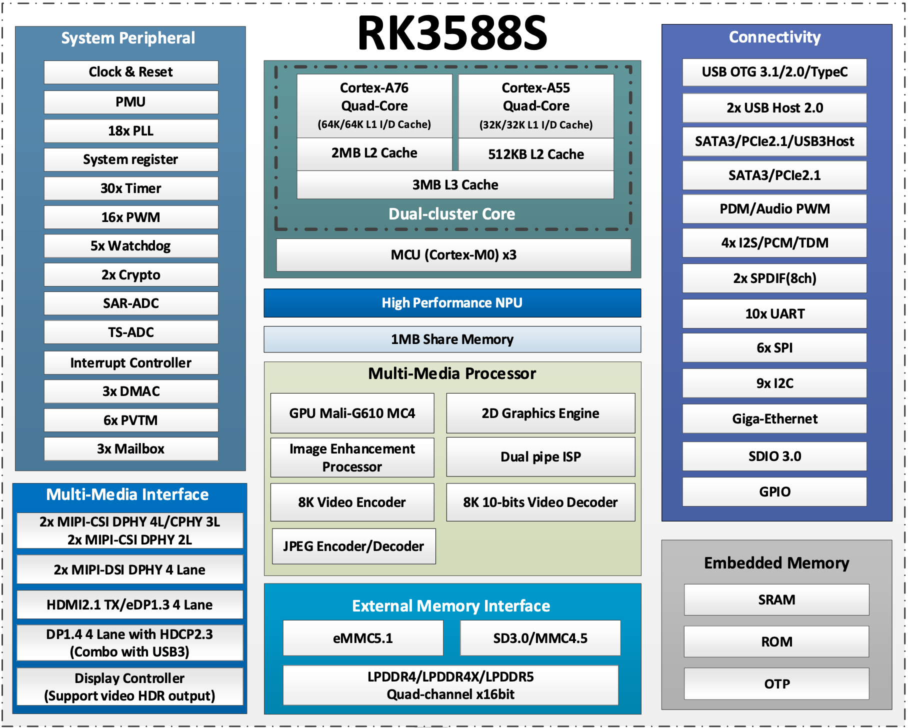
Chip block diagram
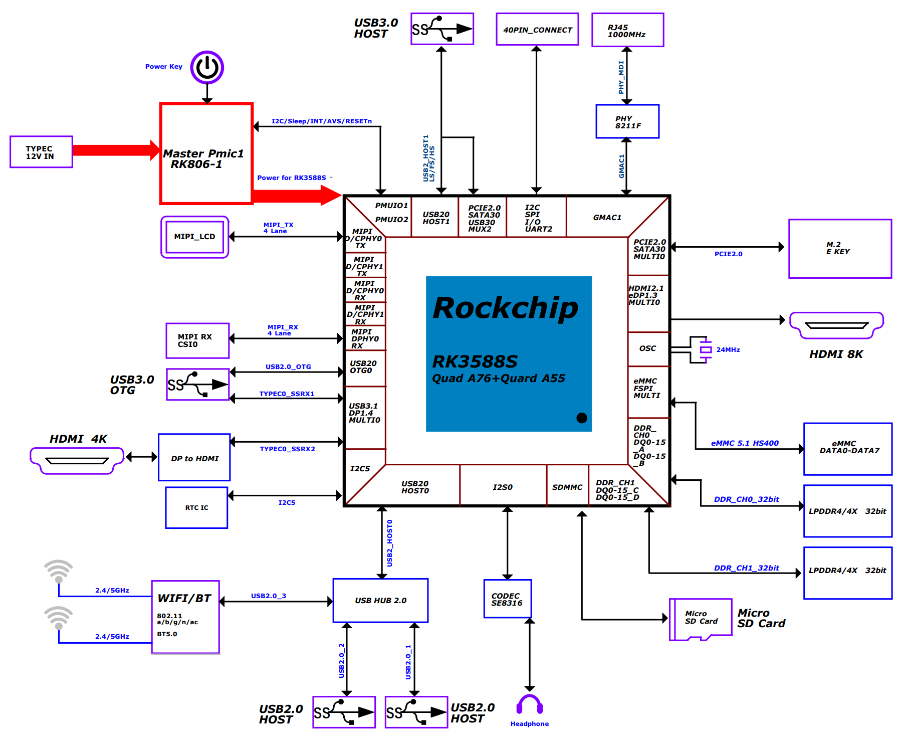
System block diagram
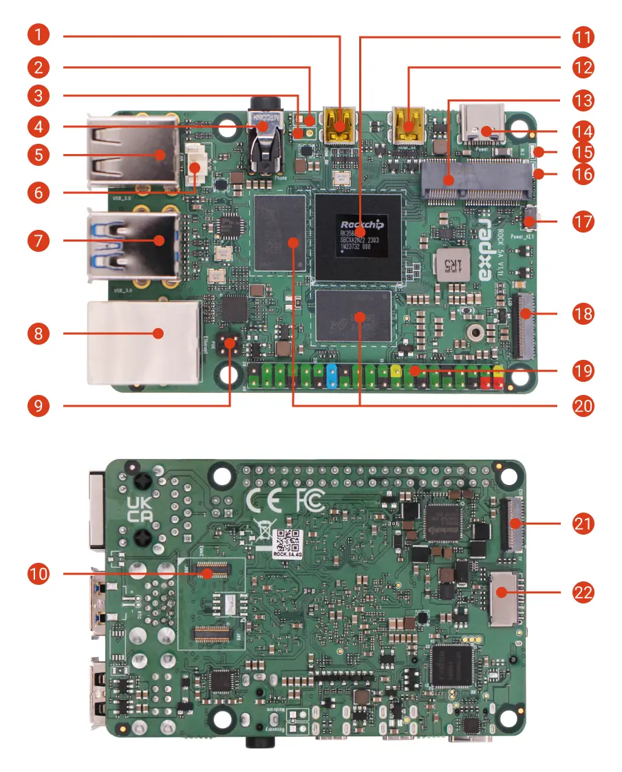
Interface Overview
| No. | Description | No. | Description | No. | Description |
|---|---|---|---|---|---|
| 1 | Micro HDMI | 2 | Reset Header (Unsoldered) | 3 | Maskrom Header (Unsoldered) |
| 4 | Headphone Jack | 5 | USB 2.0 Type-A | 6 | Fan Header |
| 7 | Up: USB 3.0 Type-A(OTG) Down: USB 3.0 Type-A(HOST) | 8 | Gigabit Ethernet port - Supports PoE, requires PoE HAT | 9 | PoE Header |
| 10 | eMMC & SPI Flash Connector | 11 | Rockchip RK3588S SoC | 12 | Micro HDMI |
| 13 | M.2 E Key 2230 Slot | 14 | USB Type-C Power | 15 | Status LED |
| 16 | Power LED | 17 | Power Button | 18 | MIPI DSI |
| 19 | 40-Pin GPIO Header | 20 | LPDDR4X Memory | 21 | MIPI CSI |
| 22 | microSD Card Slot |
Interface Details
40-Pin GPIO Header
The ROCK 5A features an onboard 40-pin GPIO (General Purpose Input/Output) header, providing flexible hardware expansion.
GPIO Functions
- x1.2/v1.1
- x1.1
| GPIO number | Function7 | Function6 | Function5 | Function4 | Function3 | Function2 | Function1 | Pin# | Pin# | Function1 | Function2 | Function3 | Function4 | Function5 | Function6 | Function7 | GPIO number |
|---|---|---|---|---|---|---|---|---|---|---|---|---|---|---|---|---|---|
| +3.3V | 1 | 2 | +5.0V | ||||||||||||||
| 63 | PWM15_IR_M3 | I2C8_SDA_M2 | GPIO1_D7 | 3 | 4 | +5.0V | |||||||||||
| 62 | PWM14_M2 | I2C8_SCL_M2 | GPIO1_D6 | 5 | 6 | GND | |||||||||||
| 43 | UART4_TX_M2 | GPIO1_B3 | 7 | 8 | GPIO0_B5 | UART2_TX_M0 | I2C1_SCL_M0 | I2S1_MCLK_M1 | 13 | ||||||||
| GND | 9 | 10 | GPIO0_B6 | UART2_RX_M0 | I2C1_SDA_M0 | I2S1_SCLK_M1 | 14 | ||||||||||
| 139 | I2S1_SDO2_M0 | PWM15_IR_M1 | I2C7_SDA_M3 | UART8_CTSN_M0 | GPIO4_B3 | 11 | 12 | GPIO4_A1 | I2S1_SCLK_M0 | SPI0_MOSI_M1 | 129 | ||||||
| 138 | SPI0_CS0_M1 | I2S1_SDO1_M0 | PWM14_M1 | I2C7_SCL_M3 | UART8_RTSN_M0 | GPIO4_B2 | 13 | 14 | GND | ||||||||
| 140 | I2S1_SDO3_M0 | SPDIF0_TX_M1 | PWM11_IR_M1 | GPIO4_B4 | 15 | 16 | GPIO1_A5 | SPI2_MOSI_M0 | 37 | ||||||||
| +3.3V | 17 | 18 | GPIO1_B0 | SPI2_CS1_M0 | 40 | ||||||||||||
| 33 | SPI4_MOSI_M2 | I2C2_SCL_M4 | UART6_TX_M1 | GPIO1_A1 | 19 | 20 | GND | ||||||||||
| 32 | SPI4_MISO_M2 | I2C2_SDA_M4 | UART6_RX_M1 | GPIO1_A0 | 21 | 22 | GPIO1_B5 | UART7_TX_M2 | SPI0_CS1_M2 | 45 | |||||||
| 34 | SPI4_CLK_M2 | PWM0_M2 | I2C4_SDA_M3 | UART6_RTSN_M1 | GPIO1_A2 | 23 | 24 | GPIO1_A3 | UART6_CTSN_M1 | I2C4_SCL_M3 | PWM1_M2 | SPI4_CS0_M2 | 35 | ||||
| GND | 25 | 26 | GPIO1_A4 | SPI2_MISO_M0 | 36 | ||||||||||||
| 23 | SPI0_MISO_M0 | I2S1_SDI2_M1 | PWM6_M0 | I2C6_SDA_M0 | GPIO0_C7 | 27 | 28 | GPIO0_D0 | I2C6_SCL_M0 | PWM7_IR_M0 | I2S1_SDI3_M1 | SPI3_MISO_M2 | 24 | ||||
| 42 | SPI0_MOSI_M2 | UART4_RX_M2 | GPIO1_B2 | 29 | 30 | GND | |||||||||||
| 41 | SPI0_MISO_M2 | GPIO1_B1 | 31 | 32 | GPIO4_B0 | UART8_TX_M0 | I2C6_SDA_M3 | I2S1_SDI3_M0 | SPI2_CS1_M1 | 136 | |||||||
| 44 | SPI0_CS0_M2 | UART7_RX_M2 | GPIO1_B4 | 33 | 34 | GND | |||||||||||
| 128 | SPI0_MISO_M1 | I2S1_MCLK_M0 | GPIO4_A0 | 35 | 36 | GPIO4_A2 | I2S1_LRCK_M0 | SPI0_CLK_M1 | 130 | ||||||||
| SARADC_VIN2 | 37 | 38 | GPIO4_A5 | I2C3_SDA_M2 | I2S1_SDI0_M0 | 133 | |||||||||||
| GND | 39 | 40 | GPIO4_B1 | UART8_RX_M0 | I2C6_SCL_M3 | SPDIF1_TX_M1 | I2S1_SDO0_M0 | SPI0_CS1_M1 | 137 |
| GPIO number | Function6 | Function5 | Function4 | Function3 | Function2 | Function1 | Pin# | Pin# | Function1 | Function2 | Function3 | Function4 | Function5 | Function6 | Function7 | GPIO number |
|---|---|---|---|---|---|---|---|---|---|---|---|---|---|---|---|---|
| +3.3V | 1 | 2 | +5.0V | |||||||||||||
| 32 | UART6_RX | SPI4_MISO | I2C2_SDA | GPIO1_A0 | 3 | 4 | +5.0V | |||||||||
| 33 | UART6_TX | SPI4_MOSI | I2C2_SCL | GPIO1_A1 | 5 | 6 | GND | |||||||||
| 43 | PDM1_CLK1 | UART4_TX | SPI0_CLK | GPIO1_B3 | 7 | 8 | GPIO0_B5 | UART2_TX_M0 | I2C1_SCL | I2S1_MCLK | 13 | |||||
| GND | 9 | 10 | GPIO0_B6 | UART2_RX_M0 | I2C1_SDA | I2S1_SCLK | 14 | |||||||||
| 34 | PWM0 | UART6_RTS | SPI4_CLK | I2C4_SDA | GPIO1_A2 | 11 | 12 | GPIO4_A1 | SPI0_MOSI | I2S1_SCLK | 129 | |||||
| 35 | PWM1 | UART6_CTS | SPI4_CS0 | I2C4_SCL | GPIO1_A3 | 13 | 14 | GND | ||||||||
| 140 | I2S1_SDO3 | SPDIF0_TX | PWM11 | GPIO4_B4 | 15 | 16 | GPIO1_D6 | I2C8_SCL | PWM14 | 62 | ||||||
| +3.3V | 17 | 18 | GPIO1_D7 | I2C8_SDA | PWM15 | 63 | ||||||||||
| 37 | SPI2_MOSI | GPIO1_A5 | 19 | 20 | GND | |||||||||||
| 36 | SPI2_MISO | GPIO1_A4 | 21 | 22 | GPIO1_B5 | SPI0_CS1 | 45 | |||||||||
| 38 | SPI2_CLK | GPIO1_A6 | 23 | 24 | GPIO1_A7 | SPI2_CS0 | PDM1_SDI0 | PWM3 | 39 | |||||||
| GND | 25 | 26 | SARADC_VIN5 | |||||||||||||
| 139 | I2S1_SDO2 | PWM15 | UART8_CTS | I2C7_SDA | GPIO4_B3 | 27 | 28 | GPIO4_B2 | I2C7_SCL | SPI0_CS0 | UART8_RTS | PWM14 | I2S1_SDO1 | 138 | ||
| 42 | PDM1_SDI3 | UART4_RX | SPI0_MOSI | GPIO1_B2 | 29 | 30 | GND | |||||||||
| 41 | PDM1_SDI2 | SPI0_MISO | GPIO1_B1 | 31 | 32 | GPIO4_B0 | I2C6_SDA | UART8_TX | I2S1_SDI3 | 136 | ||||||
| 44 | PDM1_CLK0 | GPIO1_B4 | 33 | 34 | GND | |||||||||||
| 128 | I2S1_MCLK | SPI0_MISO | GPIO4_A0 | 35 | 36 | GPIO4_A2 | SPI0_CLK | I2S1_LRCK | 130 | |||||||
| 40 | PDM1_SDI1 | SPI2_CS1 | GPIO1_B0 | 37 | 38 | GPIO4_A5 | I2C3_SDA | I2S1_SDI0 | 133 | |||||||
| GND | 39 | 40 | GPIO4_B1 | I2C6_SCL | SPI0_CS1 | UART8_RX | SPDIF1_TX | I2S1_SDO0 | 137 |
USB function configuration on 40-pin header
On the ROCK 5A 40-pin header, the following pins can be configured for USB 2.0:
- USB4_DM: pin 28, resistor location R104.
- USB4_DP: pin 27, resistor location R106.
By default, pin 27 can be configured in software for functions such as GPIO0_C7 (see the 40-pin pinout), while the USB4_DP signal is not enabled in hardware. Pin 28 can be configured in software for functions such as GPIO0_D0 (see the 40-pin pinout), and the USB4_DM signal is also not enabled in hardware. To switch these pins to USB mode, modify the reserved resistors as follows:
- Remove the 0-ohm resistors at R169 and R170.
- Solder 0-ohm resistors to R104 and R106.
Schematics and reference designators are available in the hardware resources: Hardware download
This operation requires soldering skills. It is recommended to be performed by experienced technicians.
Gigabit Ethernet
The ROCK 5A features one onboard Gigabit Ethernet port. It supports Power over Ethernet (PoE) when used with a PoE HAT, and provides 10/100/1000 Mbps auto-negotiation.
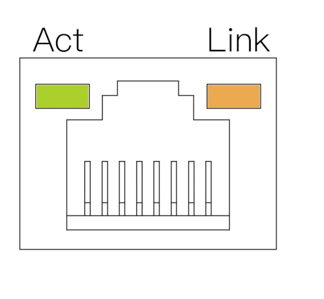
| LED | Status | Description |
|---|---|---|
| Orange | On | Link established (connected to network) |
| Green | Blink | Data transmission (network activity) |
| Off | - | No link detected (cable unplugged or network issue) |
USB
The ROCK 5A features two USB 2.0 Type-A ports, two USB 3.0 Type-A ports, and one USB Type-C port.
- USB 2.0 Type-A: used for connecting USB devices such as a mouse, keyboard, or USB flash drive.
- USB 3.0 Type-A: used for connecting USB devices. One USB 3.0 port supports OTG.
- USB Type-C: power input port, compatible with PD and QC.
Fan header
The board features an onboard 2-pin 1.25 mm fan header with PWM control. You can connect an active cooler to improve heat dissipation and maintain optimal performance.
Headphone jack
The board features a 4-pole 3.5 mm headphone jack with microphone input.
Micro HDMI
The board features two Micro HDMI ports for connecting displays, with output up to 8K@60Hz.
eMMC & SPI Flash connector
Supports installing either an eMMC module or an SPI Flash module. The two are mutually exclusive, and only one can be installed at a time.
M.2 E Key connector
Supports installing an M.2 E Key 2230 Wi-Fi/Bluetooth module.
Status LEDs
The board includes one power LED and one status LED.
- Power LED: solid green indicates normal power.
- Status LED: blinking blue indicates normal system boot.
Power button
Used to control the system power state (power on/off).
MIPI CSI
The board features one 4-lane MIPI CSI connector for connecting MIPI CSI cameras.
MIPI CSI connector specifications:
- Connector type: 31-pin, 0.3 mm pitch, SMD right-angle FPC connector
- Connection: flip-lock, bottom contact
MIPI DSI
The board features one MIPI DSI connector for connecting MIPI DSI displays.
MIPI DSI connector specifications:
- Connector type: 39-pin, 0.3 mm pitch, SMD right-angle FPC connector
- Connection: flip-lock, bottom contact
Maskrom Header
Short the Maskrom header before powering on the board, then power it using a power adapter to enter Maskrom mode.
Recovery Header
Short the Recovery header before powering on the board, then power it using a power adapter to enter Recovery mode.