MIPI CSI
MIPI CSI Interface
Support List
| Camera Name | Sensor Model | Resolution |
|---|---|---|
| OKDO 5MP Camera | OV5647 | 5 million pixels |
| Radxa Camera 8M 219 | IMX219 | 8 million pixels |
| Raspberry Pi Camera V2 | IMX219 | 8 million pixels |
| Raspberry Pi Camera v1.3 | OV5647 | 5 million pixels |
Accessory usage
Radxa Camera 8M 219
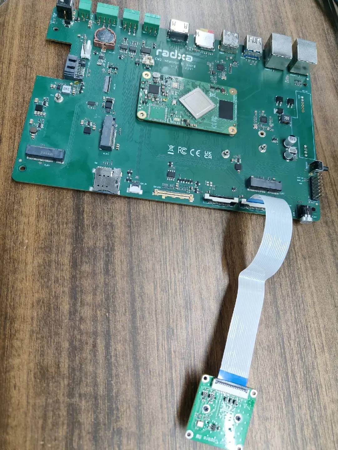
- Hardware Connection
Connect Radxa CM3I IO Board using the FPC cable as shown below:
- Lift the MIPI CSI interface latches on both the board and camera module to the unlocked position.
- Insert one end of the FPC cable into the board's MIPI CSI interface, then press down the latch to secure it after ensuring the cable is fully seated.
- Insert the other end of the cable into the camera module's MIPI CSI interface, then press down the latch to secure it after ensuring full insertion.
- Double-check that all latches on both the board and camera ends are securely locked, and that the cable lies flat without any twists.
- Ensure the device is powered off before installation.
- When connecting to the board's MIPI CSI interface, the gold fingers (metal contacts) of the cable should face the board's PCB.
- When connecting to the camera module's MIPI CSI interface, the gold fingers should face the camera's PCB.
- Avoid using excessive force during installation; ensure the cable is fully inserted before locking the latches to prevent damage to the cable or connectors.
-
Enable Overlay
- Open the Kconsole terminal via the Application Launcher in the lower left corner and run the rsetup command:
radxa@radxa-cm3i-io:~$ rsetup
- Enable Radxa Camera 8M 219 Overlay by Device Tree Configuration .
tipPlease enable [] Enable Radxa Camera 8M 219 on CAM1 Overlay。
Exit and reboot after enabling the successful display of [*] Enable Radxa Camera 8M 219 on CAM1 for the configuration to take effect.- Reboot
-
Test
- Preview
Open a terminal and enter the following command to open the camera preview:
gst-launch-1.0 v4l2src device=/dev/video0 io-mode=4 ! videoconvert ! video/x-raw,format=NV12,width=1920,height=1080 ! xvimagesink;
- Take a picture
Open a terminal and enter the following command to turn on the camera to take a picture:
gst-launch-1.0 v4l2src device=/dev/video0 io-mode=4 ! videoconvert ! video/x-raw,format=NV12,width=1920,height=1080 ! jpegenc ! multifilesink location=file.name.jpg;
- Shooting videos
Open a terminal and enter the following command to turn the camera on to capture video:
gst-launch-1.0 v4l2src num-buffers=512 device=/dev/video0 io-mode=4 ! videoconvert ! video/x-raw, format=NV12, width=1920, height=1080, framerate=30/1 ! tee name=t ! queue ! mpph264enc ! queue ! h264parse ! mpegtsmux ! filesink location=/home/radxa/file.name.mp4
Raspberry Pi Camera V2
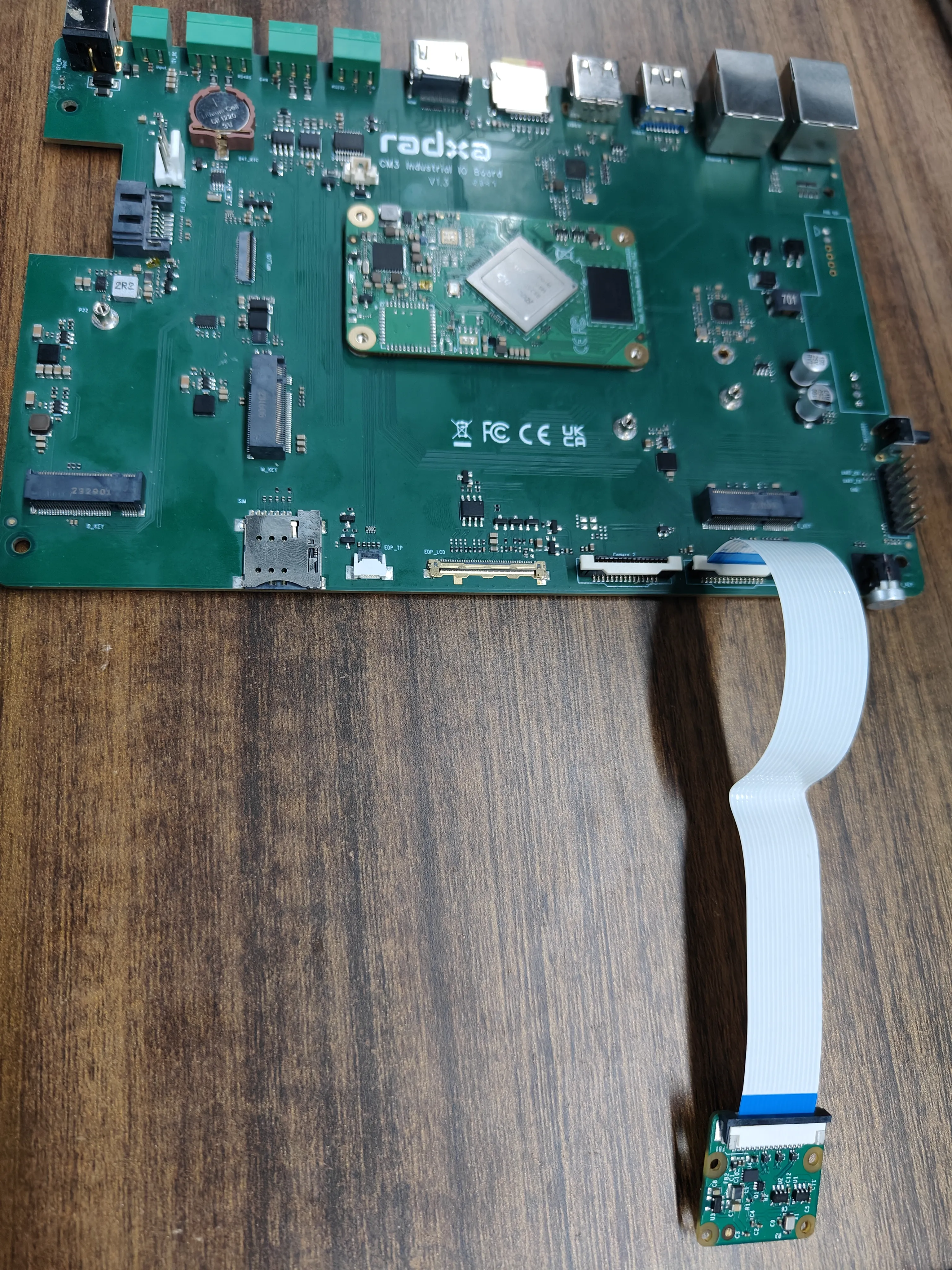
- Hardware Connection
Connect Radxa CM3I IO Board using the FPC cable as shown below:
- Lift the MIPI CSI interface latches on both the board and camera module to the unlocked position.
- Insert one end of the FPC cable into the board's MIPI CSI interface, then press down the latch to secure it after ensuring the cable is fully seated.
- Insert the other end of the cable into the camera module's MIPI CSI interface, then press down the latch to secure it after ensuring full insertion.
- Double-check that all latches on both the board and camera ends are securely locked, and that the cable lies flat without any twists.
- Ensure the device is powered off before installation.
- When connecting to the board's MIPI CSI interface, the gold fingers (metal contacts) of the cable should face the board's PCB.
- When connecting to the camera module's MIPI CSI interface, the gold fingers should face the camera's PCB.
- Avoid using excessive force during installation; ensure the cable is fully inserted before locking the latches to prevent damage to the cable or connectors.
-
Enable Overlay
- Open the Kconsole terminal via the Application Launcher in the lower left corner and run the rsetup command:
radxa@radxa-cm3i-io:~$ rsetup
- Enable Raspberry Pi Camera V2 Overlay by Device Tree Configuration .
tipPlease enable [] Enable Raspberry Pi Camera v2 on CAM1 Overlay。
Exit and reboot after enabling the successful display of [*] Enable Raspberry Pi Camera v2 on CAM1 for the configuration to take effect.- Reboot
-
Test
- Preview
Open a terminal and enter the following command to open the camera preview:
gst-launch-1.0 v4l2src device=/dev/video0 io-mode=4 ! videoconvert ! video/x-raw,format=NV12,width=1920,height=1080 ! xvimagesink;
- Take a picture
Open a terminal and enter the following command to turn on the camera to take a picture:
gst-launch-1.0 v4l2src device=/dev/video0 io-mode=4 ! videoconvert ! video/x-raw,format=NV12,width=1920,height=1080 ! jpegenc ! multifilesink location=file.name.jpg;
- Shooting videos
Open a terminal and enter the following command to turn the camera on to capture video:
gst-launch-1.0 v4l2src num-buffers=512 device=/dev/video0 io-mode=4 ! videoconvert ! video/x-raw, format=NV12, width=1920, height=1080, framerate=30/1 ! tee name=t ! queue ! mpph264enc ! queue ! h264parse ! mpegtsmux ! filesink location=/home/radxa/file.name.mp4
Raspberry Pi Camera v1.3
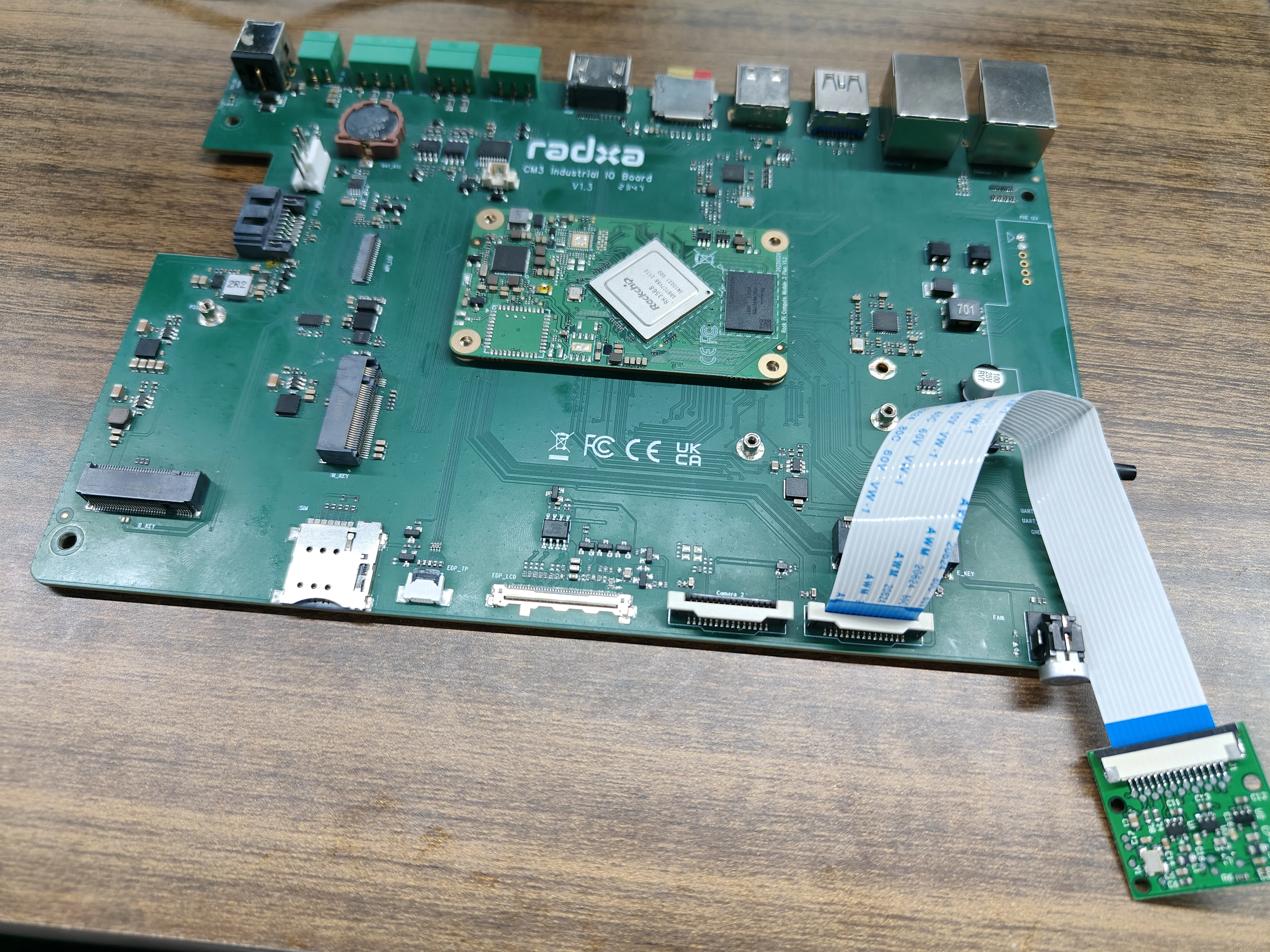
- Hardware Connection
Connect Radxa CM3I IO Board using the FPC cable as shown below:
- Lift the MIPI CSI interface latches on both the board and camera module to the unlocked position.
- Insert one end of the FPC cable into the board's MIPI CSI interface, then press down the latch to secure it after ensuring the cable is fully seated.
- Insert the other end of the cable into the camera module's MIPI CSI interface, then press down the latch to secure it after ensuring full insertion.
- Double-check that all latches on both the board and camera ends are securely locked, and that the cable lies flat without any twists.
- Ensure the device is powered off before installation.
- When connecting to the board's MIPI CSI interface, the gold fingers (metal contacts) of the cable should face the board's PCB.
- When connecting to the camera module's MIPI CSI interface, the gold fingers should face the camera's PCB.
- Avoid using excessive force during installation; ensure the cable is fully inserted before locking the latches to prevent damage to the cable or connectors.
-
Enable Overlay
- Open the Kconsole terminal via the Application Launcher in the lower left corner and run the rsetup command:
radxa@radxa-cm3i-io:~$ rsetup
- Enable Raspberry Pi Camera v1.3 Overlay by Device Tree Configuration .
tipPlease enable [] Enable Raspberry Pi Camera v1.3 on CAM1 Overlay。
Exit and reboot after enabling the successful display of [*] Enable Raspberry Pi Camera v1.3 on CAM1 for the configuration to take effect.- Reboot
-
Test
- Preview
Open a terminal and enter the following command to open the camera preview:
gst-launch-1.0 v4l2src device=/dev/video0 io-mode=4 ! videoconvert ! video/x-raw,format=NV12,width=1920,height=1080 ! xvimagesink;
- Take a picture
Open a terminal and enter the following command to turn on the camera to take a picture:
gst-launch-1.0 v4l2src device=/dev/video0 io-mode=4 ! videoconvert ! video/x-raw,format=NV12,width=1920,height=1080 ! jpegenc ! multifilesink location=file.name.jpg;
- Shooting videos
Open a terminal and enter the following command to turn the camera on to capture video:
gst-launch-1.0 v4l2src num-buffers=512 device=/dev/video0 io-mode=4 ! videoconvert ! video/x-raw, format=NV12, width=1920, height=1080, framerate=30/1 ! tee name=t ! queue ! mpph264enc ! queue ! h264parse ! mpegtsmux ! filesink location=/home/radxa/file.name.mp4