Hardware Information
Chip Block Diagram
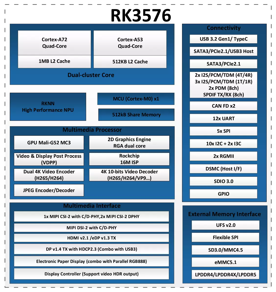
System Block Diagram
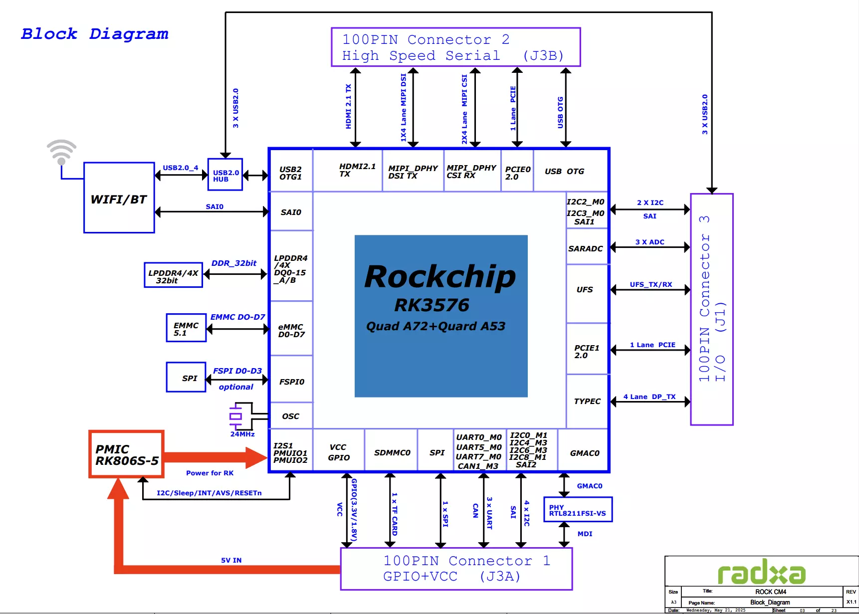
Interface Information
- CM4 Module
- CM4 IO Board
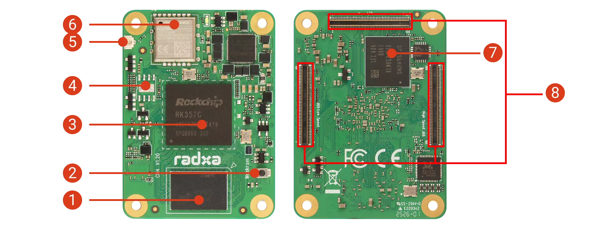
| No. | Description | No. | Description | No. | Description | No. | Description |
|---|---|---|---|---|---|---|---|
| ① | LPDDR4X RAM | ③ | SoC: Rockchip RK3576(J) | ⑤ | Antenna Connector | ⑦ | Onboard eMMC |
| ② | Maskrom Button | ④ | SPI Flash (unsoldered) | ⑥ | WiFi/BT Chip | ⑧ | 3x 100 Pin B2B Connectors |
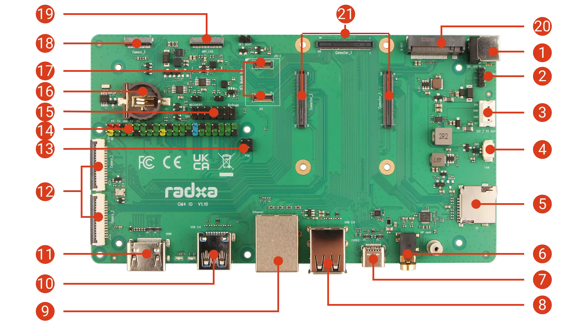
| No. | Description | No. | Description | No. | Description |
|---|---|---|---|---|---|
| ① | DC 12V Input | ⑧ | USB 2.0 Type-A Port | ⑮ | 14 Pin GPIO Header |
| ② | Power Header (for shutdown/reboot) | ⑨ | Gigabit Ethernet (PoE supported with PoE HAT) | ⑯ | RTC Interface |
| ③ | Power Output | ⑩ | USB 3.0 Type-A Port | ⑰ | UFS Module Interface |
| ④ | Fan Connector | ⑪ | HDMI Port | ⑱ | 4-lane MIPI CSI Interface |
| ⑤ | microSD Card Slot | ⑫ | 2x 2-lane MIPI CSI Interfaces | ⑲ | 4-lane MIPI DSI Interface |
| ⑥ | Headphone Jack | ⑬ | PoE Interface | ⑳ | M.2 M Key 2280 Slot |
| ⑦ | 2x USB 3.0 Type-C Ports | ⑭ | 40 Pin GPIO Header | ㉑ | 3x 100 Pin B2B Connectors |
Power Indicator
When powering the Radxa CM4 with a power adapter, the power indicator (red) on the CM4 IO Board will light up, indicating normal power supply.
The CM4's indicator will light up green when powered on. After the system runs normally, it will turn off for a few seconds, then blink in sync with the user indicator (green) on the CM4 IO Board.
User Indicator
The user indicator (green) on the Radxa CM4 blinks to indicate normal system operation.