Hardware Interface
Don't put CM5 on Radxa CM3 IO board, otherwise the board will be demanged, more info please refer faq
Interface overview
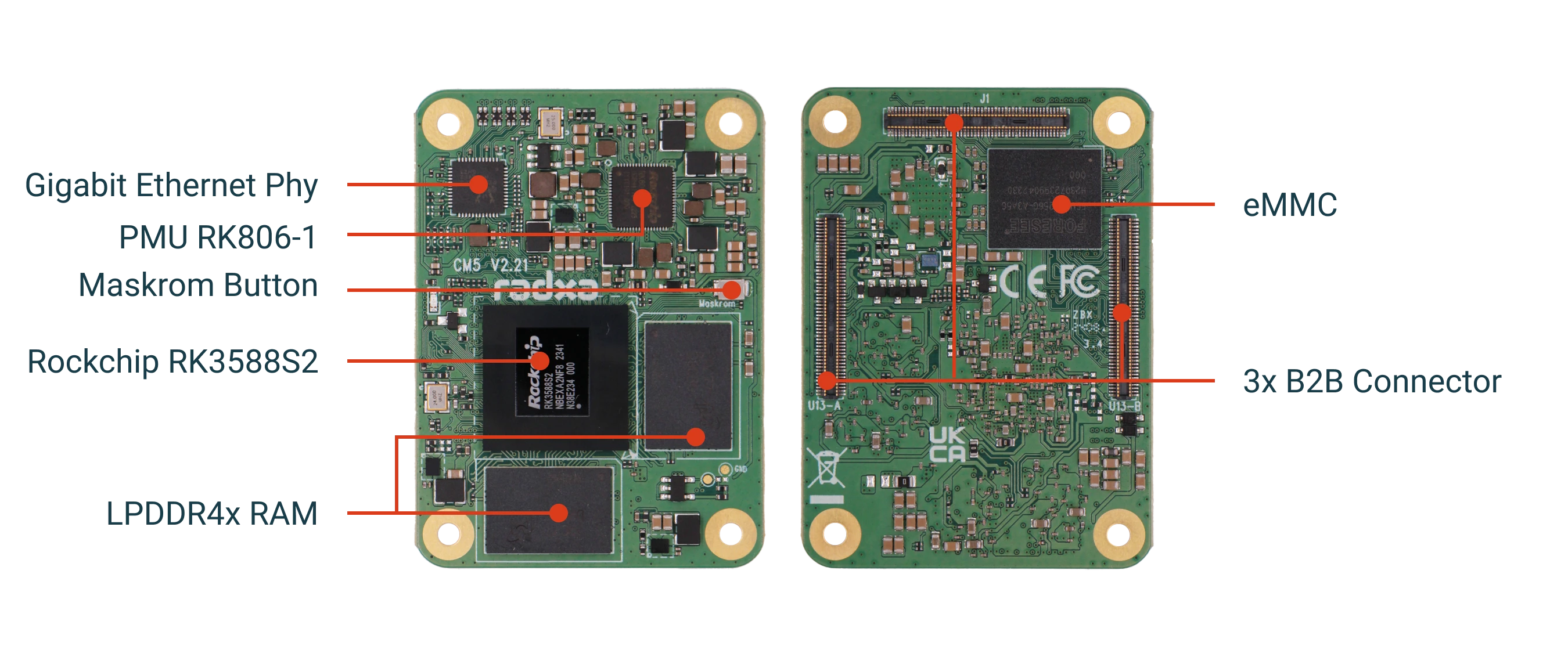
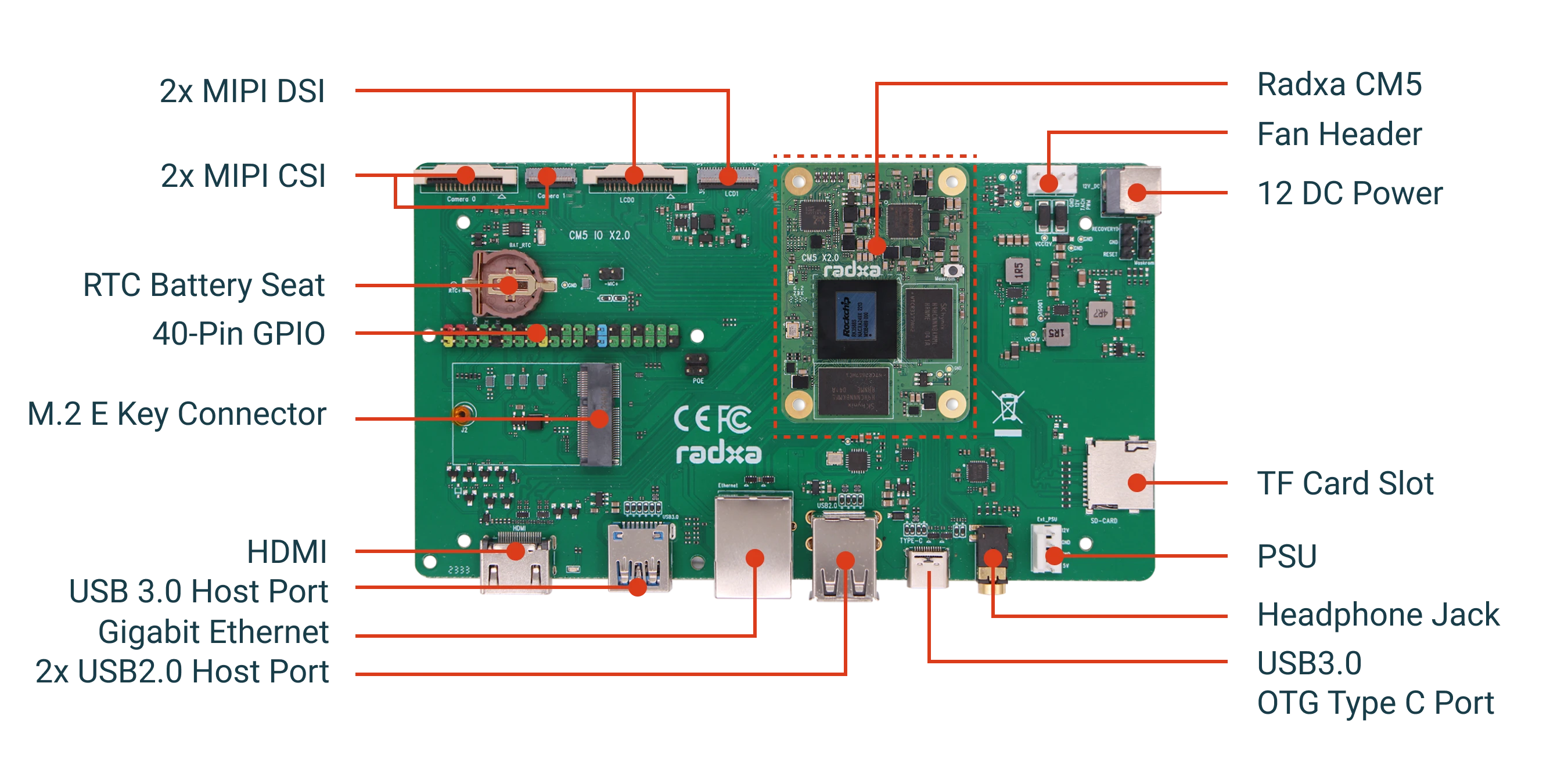
Power
The Radxa CM5 IO is powered by a DC power connector, supporting 5V and 12V inputs, 12V is recommended for a more stable power supply.
Debug Serial Port
Ethernet Port
The Radxa CM5 IO provides an Ethernet port for 1000M Ethernet.
WIFI/BT
Provides M.2 KEY interface, compatible with common PCIe protocol NICs in the market, such as Radxa Wireless A8 module.
HDMI
The Radxa CM5 IO is equipped with a full-size HDMI connector. It is recommended to use a monitor with HDMI capability.
The Radxa CM5 IO supports resolutions up to 8K, as well as regular 4K, 2K, and 1080P resolutions.
Type-C
The Radxa CM5 IO is equipped with a full-featured typec interface. Supports DP display and connection of USB-Hub devices.
USB
With USB3.0 HOST x1 and USB2.0 HOST x2.
MIPI CSI
Radxa CM5 IO Support for Camera Functions
MIPI DSI
The Radxa CM5 IO supports the MIPI DSI display function.
Radxa recommends using Radxa Display 8 HD or Radxa Display 10 FHD.
microSD
Can be used as a system boot disk or as a storage medium
Headphone jack
Supports standard 3.5mm headset (with microphone)
RTC
Connects to RTC battery, Battery Mode for CM5 IO is CR1220
40 PIN GPIO
GPIO voltage
| GPIO | Voltage | Max Voltage |
|---|---|---|
| All GPIO | 3.3V | 3.63V |
| SARADC_IN4 | 1.8V | 1.98V |
GPIO interface
Radxa CM5 IO provides a 40pin GPIO socket, which is compatible with most sensor applications on the market.
**Tips: The actual compatibility is subject to usage. **
- v2.21
| GPIO number | Function5 | Function4 | Function3 | Function2 | Function1 | Pin# | Pin# | Function1 | Function2 | Function3 | Function4 | Function5 | GPIO number |
|---|---|---|---|---|---|---|---|---|---|---|---|---|---|
| +3.3V | 1 | 2 | +5.0V | ||||||||||
| 123 | PWM10_M2 | I2C7_SDA_M2 | GPIO3_D3 | 3 | 4 | +5.0V | |||||||
| 122 | I2C7_SCL_M2 | GPIO3_D2 | 5 | 6 | GND | ||||||||
| 135 | I2S1_SDI2_M0 | I2C5_SDA_M2 | GPIO4_A7 | 7 | 8 | GPIO0_B5 | UART2_TX_M0 | 13 | |||||
| GND | 9 | 10 | GPIO0_B6 | UART2_RX_M0 | 14 | ||||||||
| 134 | I2S1_SDI1_M0 | UART3_RX_M2 | I2C5_SCL_M2 | GPIO4_A6 | 11 | 12 | GPIO0_C2 | 18 | |||||
| 133 | I2S1_SDI0_M0 | UART3_TX_M2 | I2C3_SDA_M2 | GPIO4_A5 | 13 | 14 | GND | ||||||
| 132 | I2C3_SCL_M2 | GPIO4_A4 | 15 | 16 | GPIO1_C4 | SPI4_CS1_M0 | PWM11_IR_M2 | 52 | |||||
| +3.3V | 17 | 18 | GPIO1_D5 | SPI1_CS1_M2 | 61 | ||||||||
| 129 | I2S1_SCLK_M0 | SPI0_MOSI_M1 | GPIO4_A1 | 19 | 20 | GND | |||||||
| 128 | I2S1_MCLK_M0 | SPI0_MISO_M1 | GPIO4_A0 | 21 | 22 | GPIO1_B1 | 41 | ||||||
| 130 | I2S1_LRCK_M0 | SPI0_CLK_M1 | GPIO4_A2 | 23 | 24 | GPIO4_B2 | SPI0_CS0_M1 | I2S1_SDO1_M0 | PWM14_M1 | 138 | |||
| GND | 25 | 26 | GPIO3_B7 | I2C3_SCL_M1 | SPI1_MOSI_M1 | 111 | |||||||
| 63 | I2C8_SDA_M2 | GPIO1_D7 | 27 | 28 | GPIO1_D6 | I2C8_SCL_M | PWM14_M2 | 62 | |||||
| 24 | I2S1_SDI3_M1 | PWM7_IR_M0 | I2C6_SAL_M0 | GPIO0_D0 | 29 | 30 | GND | ||||||
| 23 | I2S1_SDI2_M1 | PWM6_M0 | I2C6_SDA_M0 | GPIO0_C7 | 31 | 32 | GPIO1_B7 | PWM13_M2 | 47 | ||||
| 49 | GPIO1_C1 | 33 | 34 | GND | |||||||||
| 112 | I2C3_SDA_M1 | GPIO3_C0 | 35 | 36 | GPIO1_C6 | PWM15_IR_M2 | 54 | ||||||
| SARADC_VIN4 | 37 | 38 | GPIO1_D2 | SPI1_CLK_M2 | I2S0_SDI2 | I2S0_SDO3 | 58 | ||||||
| GND | 39 | 40 | GPIO0_D3 | SPI3_CLK_M2 | 27 |
Additional information about the 40-pin docking station for the v2.21 hardware version.
- The pins marked in orange are used for debug console.
- PWM: x7, PWM6 / PWM7 / PWM10 / PWM11 / PWM13 / PWM14 / PWM15
- SPI: x1, SPI0
- I2C: x5, I2C3 / I2C5 / I2C6 / I2C7 / I2C8
- UART: x2, UART2 / UART3
- ADC: x1, SARADC_VIN4