Hardware Information
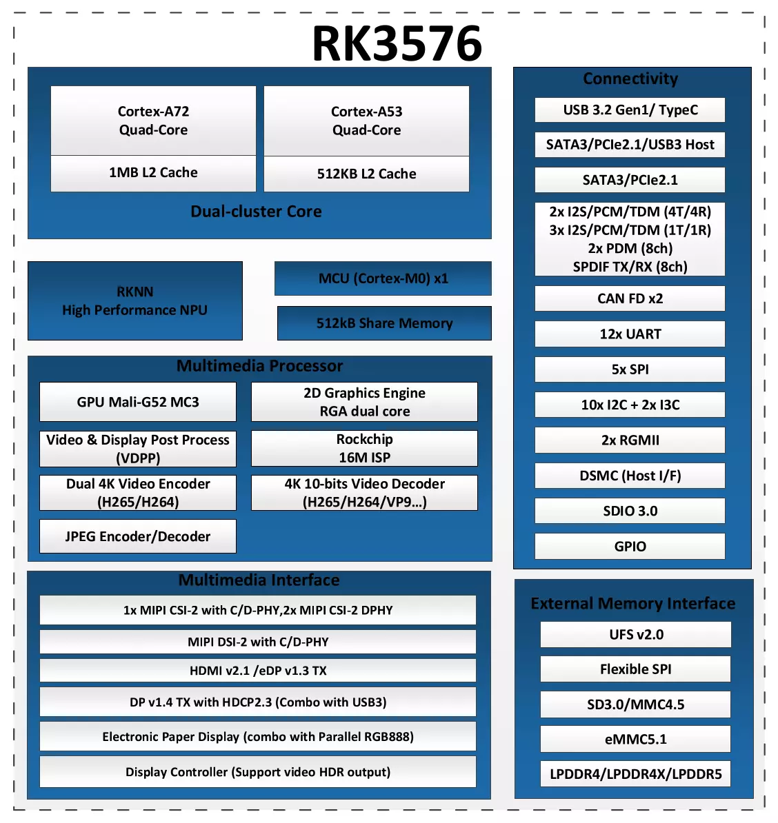
Chip block diagram
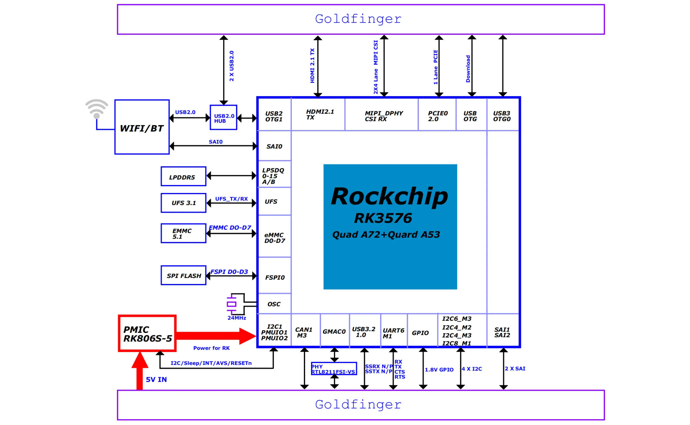
System block diagram
Interface description
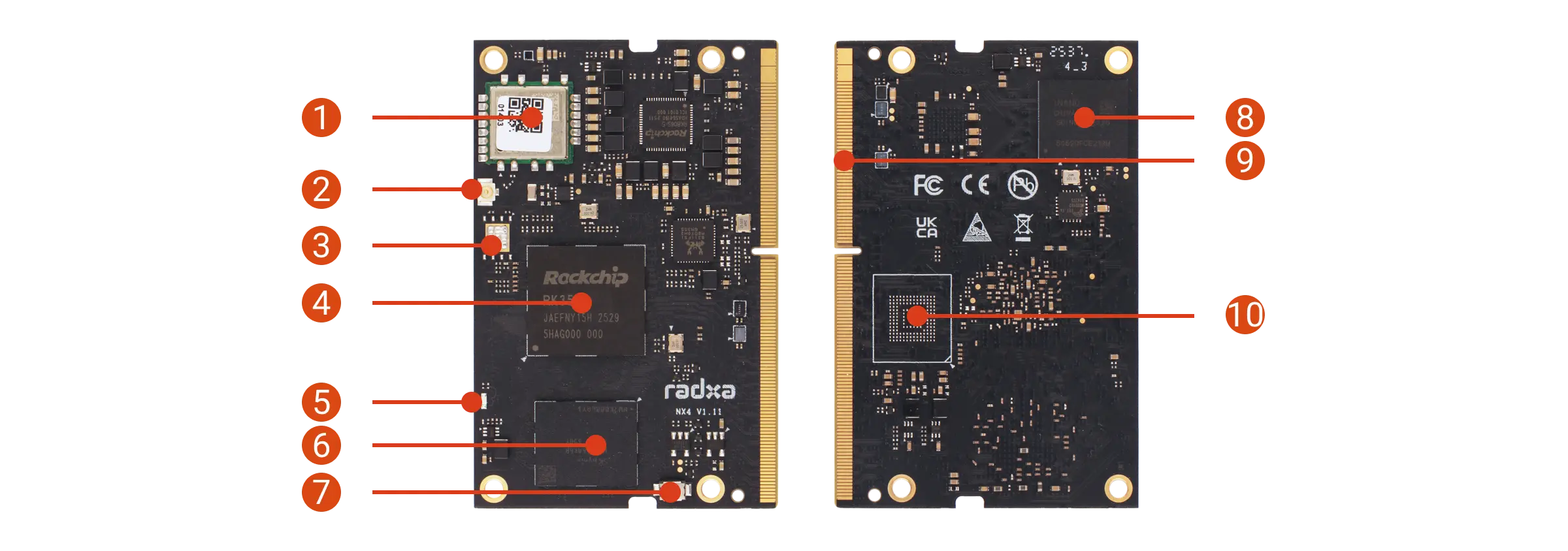
- Radxa NX4
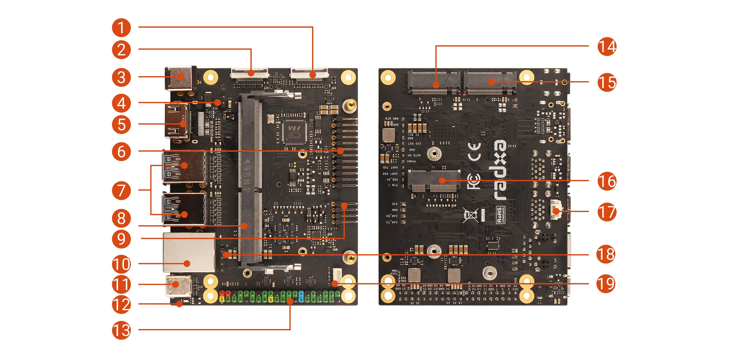
- Radxa NX4 IO Board
| No. | Description | No. | Description | No. | Description |
|---|---|---|---|---|---|
| 1 | WiFi 6 & BT 5.4 module | 2 | Antenna connector | 3 | SPI Flash (unsoldered) |
| 4 | Rockchip RK3576 | 5 | Status LED | 6 | LPDDR5 |
| 7 | Maskrom button | 8 | Onboard eMMC | 9 | 260-pin SO-DIMM connector |
| 10 | Onboard UFS (unsoldered) |
| No. | Description | No. | Description | No. | Description |
|---|---|---|---|---|---|
| 1 | MIPI CSI(4-lane) | 2 | MIPI CSI(4-lane) | 3 | DC Power Jack(9-20V) |
| 4 | PoE Backpower Header | 5 | HDMI | 6 | Button Header |
| 7 | 4x USB 3.2 Type-A | 8 | SO-DIMM Connector | 9 | CAN Bus Header |
| 10 | RJ45 Gigabit Ethernet port | 11 | USB Type-C | 12 | Power LED |
| 13 | 40-Pin GPIO Header | 14 | M.2 M Key 2230 Slot Currently not available | 15 | M.2 M Key 2280 Slot Currently not available |
| 16 | M.2 E Key 2230 Slot (PCIe 2.0 x1) | 17 | RTC Battery Connector | 18 | PoE Header |
| 19 | Fan Header |
Interface Notes
When Radxa NX4 is used with the Radxa NX4 IO Board, the M.2 M Key 2230 and M.2 E Key 2230 slots are not available.
- Power LED
Under normal conditions, the power LED (green) on the Radxa NX4 IO Board turns on, indicating that power is normal.
- User LED
The status LED (blue) on Radxa NX4 blinks, indicating that the system is running normally.