Hardware Interface Description
Interface overview
- ZERO
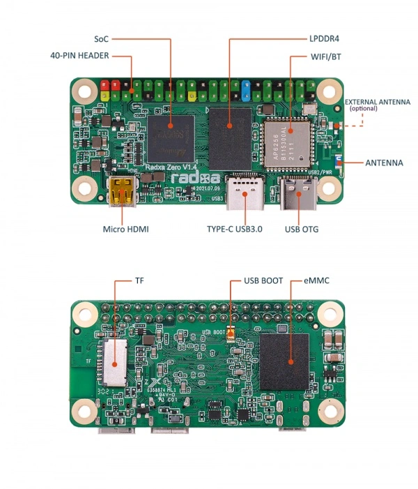
Processor
ZERO's SoC is the Amlogic S905Y2. The CPU is a quad-core ARM Cortex-A53 processor. The ARM G31 MP2 GPU makes the S905Y2 fully compatible with OpenGL ES 3.2, Vulkan 1.0 and OpenCL 2.0. The special 2.5D hardware engine will maximize display performance and provide smooth operation.
ZERO
The ZERO has a 32 bits LPDDR 4 chip.The ZERO offers 512MB, 1GB, 2GB and 4GB memory options.
USB OTG (Power Interface)
The ZERO is powered by a Type-C connector with an input voltage of 5V, recommended to use a power adapter with a rated maximum current greater than 2A.
The official Radxa Power PD 30W is recommended. 
This interface can be used to connect peripherals such as keyboard, mouse, USB flash drive and so on.
TYPE-c USB3.0
This interface can be used to connect peripherals such as keyboard, mouse, USB flash drive and so on.
40 PIN GPIO
GPIO voltage
| GPIO | Voltage | Max |
|---|---|---|
| All GPIO | 3.3V | 3.3V |
GPIO Interface
The ZERO provides a 40 pin GPIO header that is compatible with most peer accessories on the market.
**Hint: Actual compatibility is based on usage. **
Depending on the hardware version, one of the pins 35 and 38 is connected to the power LED instead of the 40-pin header. If your design uses these pins, please check the hardware version before purchasing.
GPIOAO_8 and GPIOAO_10 are available in hardware versions v1.51 and higher.
GPIOA_14 and GPIOA_15 are connected to pull-up resistors and USB-C controllers and therefore cannot be used for general GPIOs.
Pin 22 (GPIOC_7) and pin 36 (GPIOH_8) are open-drain pins. This means that they need to be connected to GND or VCC (floating state undefined), and they need an external pull-up when used as inputs. In addition, GPIOH_8 utilizes a 5V logic level.
| GPIO number | Function4 | Function3 | Function2 | Function1 | Pin# | Pin# | Function1 | Function2 | Function3 | Function4 | GPIO number |
|---|---|---|---|---|---|---|---|---|---|---|---|
| +3.3V | 1 | 2 | +5.0V | ||||||||
| 490 | I2C_EE_M3_SDA | GPIOA_14 | 3 | 4 | +5.0V | ||||||
| 491 | I2C_EE_M3_SCL | GPIOA_15 | 5 | 6 | GND | ||||||
| 415 | I2C_AO_S0_SDA | UART_AO_B_RX | I2C_AO_M0_SDA | GPIOAO_3 | 7 | 8 | GPIOAO_0 | UART_AO_A_TXD | 412 | ||
| GND | 9 | 10 | GPIOAO_1 | UART_AO_A_RXD | 413 | ||||||
| 414 | I2C_AO_S0_SCL | UART_AO_B_TX | I2C_AO_M0_SCL | GPIOAO_2 | 11 | 12 | GPIOX_9 | SPI_A_MISO | TDMA_D0 | 501 | |
| 503 | TDMA_SCLK | I2C_EE_M1_SCL | SPI_A_SCLK | GPIOX_11 | 13 | 14 | GND | ||||
| SARADC_CH1 | 15 | 16 | GPIOX_10 | SPI_A_SS0 | I2C_EE_M1_SDA | TDMA_FS | 502 | ||||
| +3.3V | 17 | 18 | GPIOX_8 | SPI_A_MOSI | PWM_C | TDMA_D1 | 500 | ||||
| 447 | SPI_B_MOSI | UART_EE_C_RTS | GPIOH_4 | 19 | 20 | GND | |||||
| 448 | PWM_F | SPI_B_MISO | UART_EE_C_CTS | GPIOH_5 | 21 | 22 | GPIOC_7 | 475 | |||
| 450 | I2C_EE_M1_SCL | SPI_B_SCLK | UART_EE_C_TX | GPIOH_7 | 23 | 24 | GPIOH_6 | UART_EE_C_RX | SPI_B_SS0 | I2C_EE_M1_SDA | 449 |
| GND | 25 | 26 | SARADC_CH2 | ||||||||
| 415 | I2C_AO_S0_SDA | UART_AO_B_RX | I2C_AO_M0_SDA | GPIOAO_3 | 27 | 28 | GPIOAO_2 | I2C_AO_M0_SCL | UART_AO_B_TX | I2C_AO_S0_SCL | 414 |
| NC | 29 | 30 | GND | ||||||||
| NC | 31 | 32 | GPIOAO_4 | PWMAO_C | 416 | ||||||
| NC | 33 | 34 | GND | ||||||||
| 420 | UART_AO_B_TX | GPIOAO_8 | 35 | 36 | GPIOH_8 | 451 | |||||
| 421 | UART_AO_B_RX | GPIOAO_9 | 37 | 38 | GPIOAO_10 | PWMAO_D | 422 | ||||
| GND | 39 | 40 | GPIOAO_11 | PWMAO_A | 423 |
GPIO numbers
- The GPIOs are divided into two groups, the GPIO AO domain and the GPIO EE domain.
AO domain: GPIOAO_0 - GPIOAO_11
EE domain: GPIOA_14 - GPIOA_15 | GPIOH_0 - GPIOH_8 | GPIOX_0 - GPIOX_19 - UART
AO Domain: UARTAO_A | UARTAO_B
EE Domain: UART_A | UART_B | UART_C
| GPIO Chips | GPIO Names | Basics | Offsets | Formulas |
|---|---|---|---|---|
| First | GPIOAO_x | 412 | 0-11 | Base + Offset |
| First | GPIOE_x | 424 | 0-2 | Base + Offset |
| Second | GPIOZ_x | 427 | 0-15 | Base + Offset |
| Second | GPIOH_x | 443 | 0-8 | Base + Offset |
| Second | BOOT_x | 452 | 0-15 | Base + Offset |
| Second | GPIOC_x | 468 | 0-7 | Base + Offset |
| Second | GPIOA_x | 476 | 0-15 | Base + Offset |
| Second | GPIOX_x | 492 | 0-19 | Base + Offset |
Micro HDMI
The Radxa ZERO has a micro HDMI video output port on board, which requires a micro HDMI to standard HDMI cable to connect to the monitor.
The resolution of the HDMI output depends on the monitor, and the Radxa ZERO will adjust to the optimal display resolution according to the monitor.
eMMC
The on-board eMMC is located on the back of the development board for eMMC booting or data storage. We offer options from none to 128GB.
WIFI/BT
ZERO has an ap6212/ap6256/aw-cm256sm WiFi/BT module on board,the specific parameters of each module are listed in the table below.
| Module Model | WLAN Standard | Supported Frequency | WLAN Nominal Maximum Throughput | Bluetooth Standard |
|---|---|---|---|---|
| ap6212 | 802.11 b/g/n | 2.4GHz | 72.2Mbps | Bluetooth 4.1 |
| ap6256 | 802.11 a/b/g/n/ac | 2.4GHz/5GHz | 433.3Mbps | Bluetooth 5.2 |
| aw-cm256sm | 802.11 a/b/g/n/ac | 2.4GHz/5GHz | 433.3Mbps | Bluetooth 4.2 |
MicroSD slot
For MicroSD card booting or data storage.
USB BOOT Button
ZERO supports Maskrom mode, which is a special operation mode where the CPU waits for commands from the USB OTG port. When you need to write image to eMMC, you need to use Maskrom button to put it into Maskrom mode.