MicroPython
我们可以使用 MicroPython 通过 RP2040 来控制 GPIO,主 CPU 通过 UART 与 RP2040 通信,然后通过 RP2040 访问 GPIO。
搭建环境
-
下载 Micro Python (推荐使用我们验证过的v1.22.0版本), 保存为 .uf2 后缀的文件。
-
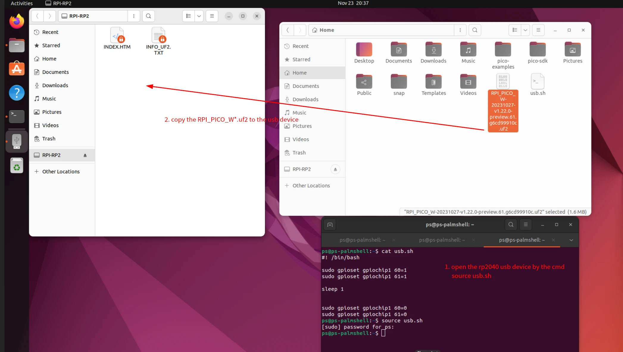
参考 烧录程序到 RP2040 打开 RP2040 设备
-
安装 Thonny IDE
sudo apt-get install thonny -y -
如下图所示将 micropython 固件拷贝到 RP2040 中
-
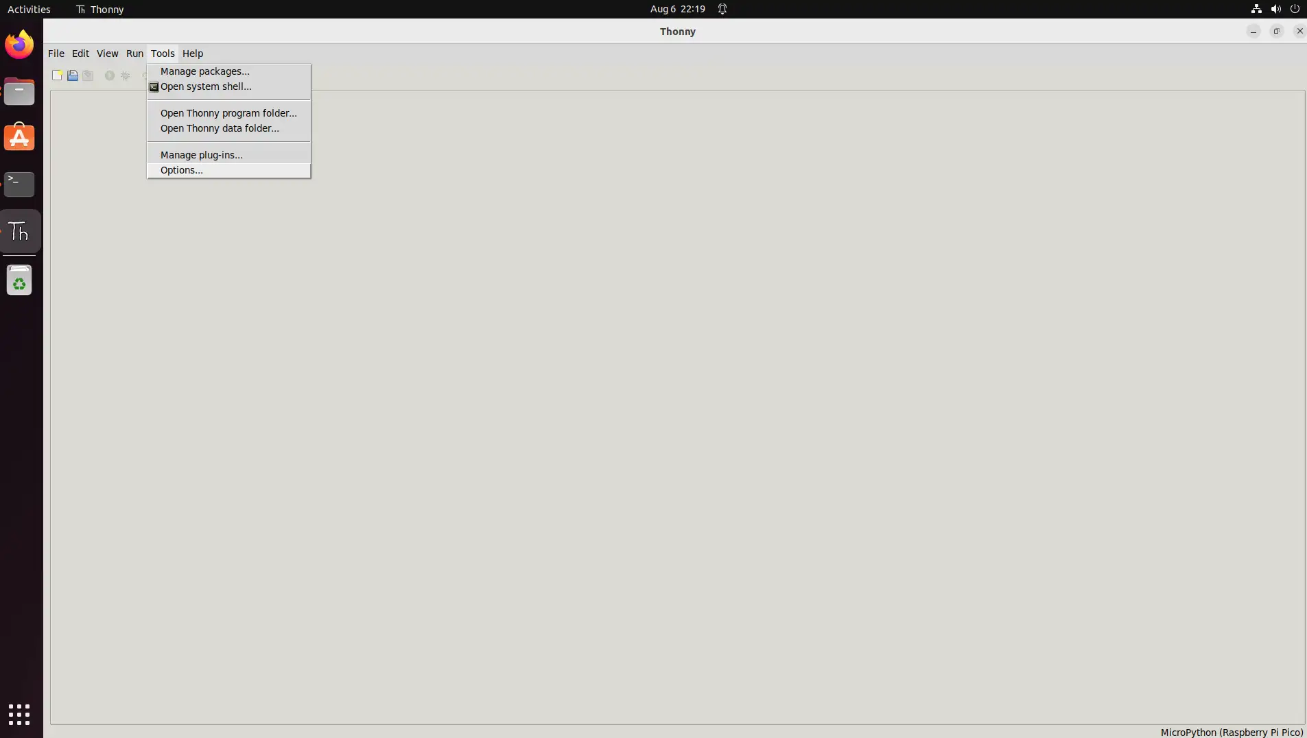
打开 Thonny IDE, 设置 micropython 解释器以及端口
-
点击上方 "Tools" 按钮,选择 "Options"
-
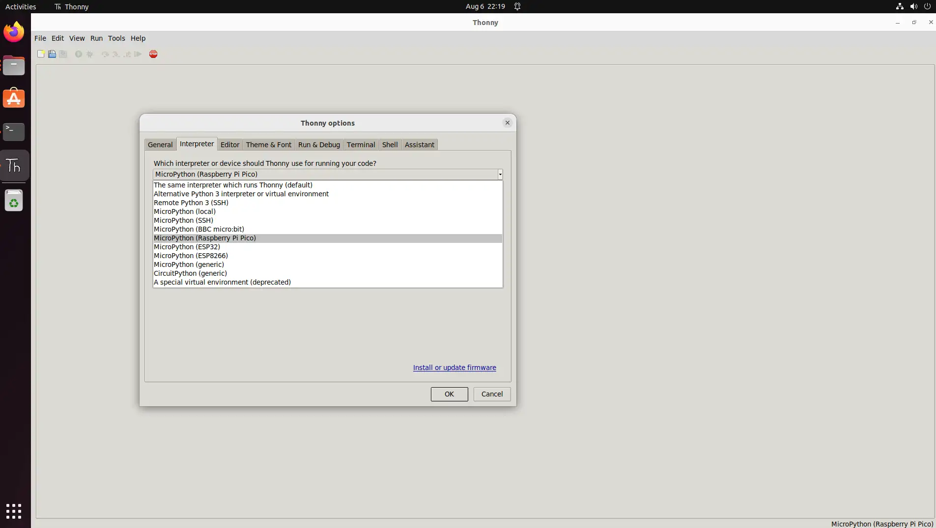
点击 "Interpreter" 选择 "MicroPython (Raspberry Pi Pico)"
 提示
提示如果没有找到 MicroPython 解释器, 请下载安装最新版本的 Thonny
-
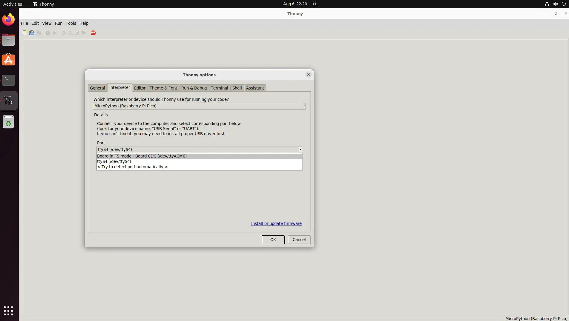
点击 "Port" 选择 "Board in FS mode - Board CDC (/dev/ttyACM0)"
-
示例
GPIO
-
准备
-
一块 Radxa X4
-
一个 Led
-
-
连接
按照以下方式连接 Radxa X4 和 Led
| Radxa X4 | <--> | Led |
|---|---|---|
| PIN_3 | <--> | S |
| PIN_1 | <--> | VCC |
| PIN_9 | <--> | GND |
- 打开 Thonny IDE, 新建一个 blink.py 文件,内容如下:
blink.py
import machine
import time

class Blinker:

def __init__(self, pin_num, interval):
        self.pin = machine.Pin(pin_num, machine.Pin.OUT)
        self.interval = interval
        self.pin.off()

    def blink(self):
        self.pin.toggle()
        time.sleep(self.interval)

def main():
    blinker = Blinker(28, 1)

    try:
        while True:
            blinker.blink()
    except KeyboardInterrupt:
        print("Blink stopped.")

if __name__ == "__main__":
    main()
-
测试
-
点击 ‘Run’ 按钮
-
Led 会隔 1 秒闪烁
-
I2C
-
准备
-
一块 Radxa X4
-
一个 OLED
-
-
连接
按照以下方式连接 Radxa X4 和 Led
Radxa X4 <--> OLED PIN_ <--> SDA PIN_ <--> SCL PIN_1 <--> VCC PIN_9 <--> GND
- 打开 Thonny IDE, 新建一个 oled.py 文件,内容如下:
oled.py
from machine import I2C, Pin
import time

# init I2C
i2c = I2C(0, scl=Pin(29), sda=Pin(28), freq=400000)

# SSD1306 I2C addr
SSD1306_I2C_ADDR = 0x3C

# init cmds
init_cmds = [
    0xAE,  # Display off
    0xA8, 0x3F,  # Set multiplex ratio (1 to 64)
    0xD3, 0x00,  # Set display offset
    0x40,  # Set display start line
    0x8D, 0x14,  # Enable charge pump regulator
    0x20, 0x00,  # Set Memory Addressing Mode to horizontal
    0xA1,  # Set segment re-map
    0xC8,  # Set COM output scan direction
    0xDA, 0x12,  # Set COM pins hardware configuration
    0x81, 0x7F,  # Set contrast control
    0xD9, 0xF1,  # Set pre-charge period
    0xDB, 0x40,  # Set VCOMH deselect level
    0xA4,  # Entire display on
    0xA6,  # Set normal display
    0xAF   # Display on
]

for cmd in init_cmds:
    i2c.writeto(SSD1306_I2C_ADDR, bytearray([0x00, cmd]))  # 0x00 is a cmd

# clear
buffer = bytearray(1024)

font = {
    'A': [0x7C, 0x12, 0x11, 0x12, 0x7C],
    'B': [0x7F, 0x49, 0x49, 0x49, 0x36],
    'C': [0x3E, 0x41, 0x41, 0x41, 0x22],
    'D': [0x7F, 0x41, 0x41, 0x41, 0x3E],
    'E': [0x7F, 0x49, 0x49, 0x49, 0x41],
    'F': [0x7F, 0x09, 0x09, 0x09, 0x01],
    'G': [0x3E, 0x41, 0x49, 0x49, 0x7A],
    'H': [0x7F, 0x08, 0x08, 0x08, 0x7F],
    'I': [0x00, 0x41, 0x7F, 0x41, 0x00],
    'J': [0x20, 0x40, 0x40, 0x3F, 0x00],
    'K': [0x7F, 0x08, 0x14, 0x22, 0x41],
    'L': [0x7F, 0x40, 0x40, 0x40, 0x40],
    'M': [0x7F, 0x02, 0x04, 0x02, 0x7F],
    'N': [0x7F, 0x04, 0x08, 0x10, 0x7F],
    'O': [0x3E, 0x41, 0x41, 0x41, 0x3E],
    'P': [0x7F, 0x09, 0x09, 0x09, 0x06],
    'Q': [0x3E, 0x41, 0x51, 0x21, 0x5E],
    'R': [0x7F, 0x09, 0x19, 0x29, 0x46],
    'S': [0x46, 0x49, 0x49, 0x49, 0x31],
    'T': [0x01, 0x01, 0x7F, 0x01, 0x01],
    'U': [0x3F, 0x40, 0x40, 0x40, 0x3F],
    'V': [0x1F, 0x20, 0x40, 0x20, 0x1F],
    'W': [0x3F, 0x40, 0x38, 0x40, 0x3F],
    'X': [0x63, 0x14, 0x08, 0x14, 0x63],
    'Y': [0x07, 0x08, 0x70, 0x08, 0x07],
    'Z': [0x61, 0x51, 0x49, 0x45, 0x43],
    'a': [0x20, 0x54, 0x54, 0x54, 0x78],
    'b': [0x7F, 0x48, 0x44, 0x44, 0x38],
    'c': [0x38, 0x44, 0x44, 0x44, 0x20],
    'd': [0x38, 0x44, 0x44, 0x48, 0x7F],
    'e': [0x38, 0x54, 0x54, 0x54, 0x18],
    'f': [0x08, 0x7E, 0x09, 0x01, 0x02],
    'g': [0x0C, 0x52, 0x52, 0x52, 0x3E],
    'h': [0x7F, 0x08, 0x04, 0x04, 0x78],
    'i': [0x00, 0x44, 0x7D, 0x40, 0x00],
    'j': [0x20, 0x40, 0x44, 0x3D, 0x00],
    'k': [0x7F, 0x10, 0x28, 0x44, 0x00],
    'l': [0x00, 0x41, 0x7F, 0x40, 0x00],
    'm': [0x7C, 0x04, 0x18, 0x04, 0x78],
    'n': [0x7C, 0x08, 0x04, 0x04, 0x78],
    'o': [0x38, 0x44, 0x44, 0x44, 0x38],
    'p': [0x7C, 0x14, 0x14, 0x14, 0x08],
    'q': [0x08, 0x14, 0x14, 0x18, 0x7C],
    'r': [0x7C, 0x08, 0x04, 0x04, 0x08],
    's': [0x48, 0x54, 0x54, 0x54, 0x20],
    't': [0x04, 0x3F, 0x44, 0x40, 0x20],
    'u': [0x3C, 0x40, 0x40, 0x20, 0x7C],
    'v': [0x1C, 0x20, 0x40, 0x20, 0x1C],
    'w': [0x3C, 0x40, 0x30, 0x40, 0x3C],
    'x': [0x44, 0x28, 0x10, 0x28, 0x44],
    'y': [0x0C, 0x50, 0x50, 0x50, 0x3C],
    'z': [0x44, 0x64, 0x54, 0x4C, 0x44],
    ' ': [0x00, 0x00, 0x00, 0x00, 0x00],
    '!': [0x00, 0x00, 0x5F, 0x00, 0x00],
    '?': [0x02, 0x01, 0x51, 0x09, 0x06],
    '.': [0x00, 0x40, 0x60, 0x00, 0x00],
    ',': [0x00, 0x80, 0x60, 0x00, 0x00],
    '-': [0x08, 0x08, 0x08, 0x08, 0x08],
    '_': [0x80, 0x80, 0x80, 0x80, 0x80],
}

# draw "Hello"
x = 0
for char in "Hello":
    glyph = font.get(char, [0x00]*5)  # get data
    for byte in glyph:
        buffer[x] = byte
        x += 1
    x += 1  # add a space

# snd data to oled
for page in range(8):
    i2c.writeto(SSD1306_I2C_ADDR, bytearray([0x00, 0xB0 + page, 0x00, 0x10])) # set page
    i2c.writeto(SSD1306_I2C_ADDR, bytearray([0x40]) + buffer[page*128:(page+1)*128])

print("Message displayed.")
PWM
-
准备
-
一块 Radxa X4
-
一个 Led
-
-
连接
按照以下方式连接 Radxa X4 和 Led
| Radxa X4 | <--> | Led |
|---|---|---|
| PIN_3 | <--> | S |
| PIN_1 | <--> | VCC |
| PIN_9 | <--> | GND |
- 打开 Thonny IDE, 新建一个 pwm_fade.py 文件,内容如下:
pwm_fade.py
import time
from machine import Pin, PWM

pwm = PWM(Pin(28))

# Set the PWM frequency.
pwm.freq(1000)

duty = 0
direction = 1

while True:
    duty += direction
    if duty > 255:
        duty = 255
        direction = -1
    elif duty < 0:
        duty = 0
        direction = 1
    pwm.duty_u16(duty * duty)
    time.sleep(0.003)
-
测试
-
点击 'Run' 按钮
-
Led 会有一个由暗到亮再由亮到暗的效果
-
FAQ
-
Q1: RP2040 崩溃了
A1: 参考 烧录程序到 RP2040 重置 RP2040
-
Q2: 烧录 micropython 固件后,仍然有其他程序在跑
A2: 将 flash_nuke.uf2 烧录到 RP2040 中,以清除 RP2040
-
Q3: ImportError: no module named
<module-name>A2: Thonny tools 栏选择 "Manage Packages", 然后安装你所需要的 Package