SPI LCD Adaptation Method
Find Drivers by IC
View IC
First of all, when we get an SPI LCD, we need to see what ICs are used on the screen.
Taking Waveshare 3.5 inch SPI LCD Model B as an example, we can find it according to the manual or the official website, the screen is equipped with two ICs.
-
Display IC: ILI9486
-
Touch IC: ADS7846
Find Driver
We can search the kernel source code for the corresponding driver based on these two ICs.
- Find ili9486 driver
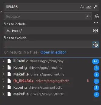
Open the kernel source code and search for the keyword “ili9486” as shown below.
According to the waveshare official website or the manual, we can know that the Waveshare 3.5 inch SPI LCD Model B is a small TFT display.
So we can identify the driver code path of this screen display IC ili9486 as: drivers/staging/fbtft/fb_ili9486.c
- Find ads7846 driver
Open the kernel source code and search for the keyword “ads7846” as shown below.
ads7846 is a touch type IC, so the driver should be in the input subsystem inside the touch screen class driver, so we can determine the screen touch IC ads7846 driver code path: drivers/input/touchscreen/ads7846.c
Prepare the Overlay development environment
- Prepare the Overlay development environment according to Overlay Development.
Write Overlay dts
The following tutorial uses the Radxa ROCK 3C as an example.
-
New a dts file named rock-3c-waveshare35.dts under the directory radxa-overlays/arch/arm64/boot/dts/rockchip/overlays/
-
Add the required header files
#include <dt-bindings/gpio/gpio.h>
#include <dt-bindings/pinctrl/rockchip.h>
#include <dt-bindings/interrupt-controller/irq.h>
- Fill in the metadata to be recognized by rsetup.
/ {
	metadata {
		title = "Enable Waveshare 3.5inch RPi LCD (C) on SPI3-M1";
		compatible = "radxa,rock-3c", "radxa,zero3";
		category = "display";
		exclusive = "GPIO4_A6", "GPIO4_C6", "GPIO3_C1", "GPIO3_B2", "GPIO3_A1", "GPIO4_D1", "GPIO4_B2", "GPIO4_B3";
		description = "Enable Waveshare 3.5inch RPi LCD (C) on SPI3-M1.
HDMI CEC function will be turned off when this overlay is enabled.";
	};
};
- Enable SPI Node
&spi3 {
	status = "okay";
	#address-cells = <1>;
	#size-cells = <0>;
	pinctrl-names = "default", "high_speed";
	pinctrl-0 = <&spi3m1_cs0 &spi3m1_pins>;
	pinctrl-1 = <&spi3m1_cs1 &spi3m1_pins_hs>;
};
Mount the ili9486 and ads7846 under this spi node requires two cs pins
- Mounting nodes
Mount ili9486 and ads7846 under spi3 node
&spi3 {
	status = "okay";
	#address-cells = <1>;
	#size-cells = <0>;
	status = "okay";
	#address-cells = <1>;
	#size-cells = <0>;
	pinctrl-names = "default", "high_speed";
	pinctrl-0 = <&spi3m1_cs0 &spi3m1_pins>;
	pinctrl-1 = <&spi3m1_cs1 &spi3m1_pins_hs>;

	ili9486: ili9486@0 {
	};

	ads7846: ads7846@1 {
	};
};
- Fill in the corresponding attributes according to the driver source code
&spi3 {
	status = "okay";
	#address-cells = <1>;
	#size-cells = <0>;
	pinctrl-names = "default", "high_speed";
	pinctrl-0 = <&spi3m1_cs0 &spi3m1_pins>;
	pinctrl-1 = <&spi3m1_cs1 &spi3m1_pins_hs>;

	ili9486: ili9486@0 {
		compatible = "ilitek,ili9486";
		reg = <0>;
		spi-max-frequency = <16000000>;
		txbuflen = <32768>;
		rotate = <90>;
		bgr = <0>;
		fps = <30>;
		buswidth = <8>;
		regwidth = <16>;
		reset-gpios = <&gpio3 RK_PC1 GPIO_ACTIVE_LOW>;
		dc-gpios = <&gpio3 RK_PB2 GPIO_ACTIVE_HIGH>;
		debug = <0>;
	};

	ads7846: ads7846@1 {
		compatible = "ti,ads7846";
		status = "okay";
		reg = <1>;
		id = <1>;
		spi-max-frequency = <2000000>;
		ti,x-plate-ohms = /bits/ 16 <60>;
		ti,pressure-max = /bits/ 16 <255>;
		ti,swap-xy = <0>;
		ti,invert-y = <1>;
		interrupts = <RK_PA1 IRQ_TYPE_EDGE_FALLING>;  // The interrupts and pendown-gpio pins need to be aligned
		interrupt-parent = <&gpio3>;
		pendown-gpio = <&gpio3 RK_PA1 GPIO_ACTIVE_HIGH>; // Fill in the specific GPIO according to the actual connection
		vcc-supply = <&vcc5v0_sys>; // Fill in the voltage according to the actual power supply circuit
	};
};
- Summary
-
The display node attribute is used on most fbtft screens, but the actual value needs to be changed according to the actual situation.
a. If the ICs are different, change the node name and compatible values. b. reset-gpios and dc-gpios need to be changed based on the actual connection.
b. reset-gpios and dc-gpios need to be changed according to the actual connection. c. The value of the debug attribute can be changed from 0~0.
c. The value of the debug attribute can be filled with a number between 0 and 7, the larger the number, the more information will be printed, the better for debugging.
-
Touch nodes need to be filled in according to the actual driver requirements.
Compile
-
Add the file name to radxa-overlays/arch/arm64/boot/dts/rockchip/overlays/Makefile
-
Compiling linux from Overlay Development Compile linux-rk356x as follows
make build-dtbo -j$(nproc) KERNELRELEASE=5.10.160-7-rk356x CONFIG_ARCH_MESON=n CONFIG_CPU_RK3399=rockchip CONFIG_CPU_RK3528=rockchip CONFIG_CPU_RK3568=rockchip CONFIG_CPU_RK3588=rockchip
Authentication
-
Connect as per dts configuration
-
Copy the file radxa-overlays/arch/arm64/boot/dts/rockchip/overlays/rock-3c-waveshare35.dtbo to the /boot/dtbo/ directory of the Radxa ROCK 3C.
- Load the Overlay with rsetup
-
Reboot to enable the Overlay
-
Test it according to the Waveshare 3.5 inch LCD documentation