Hardware interface description
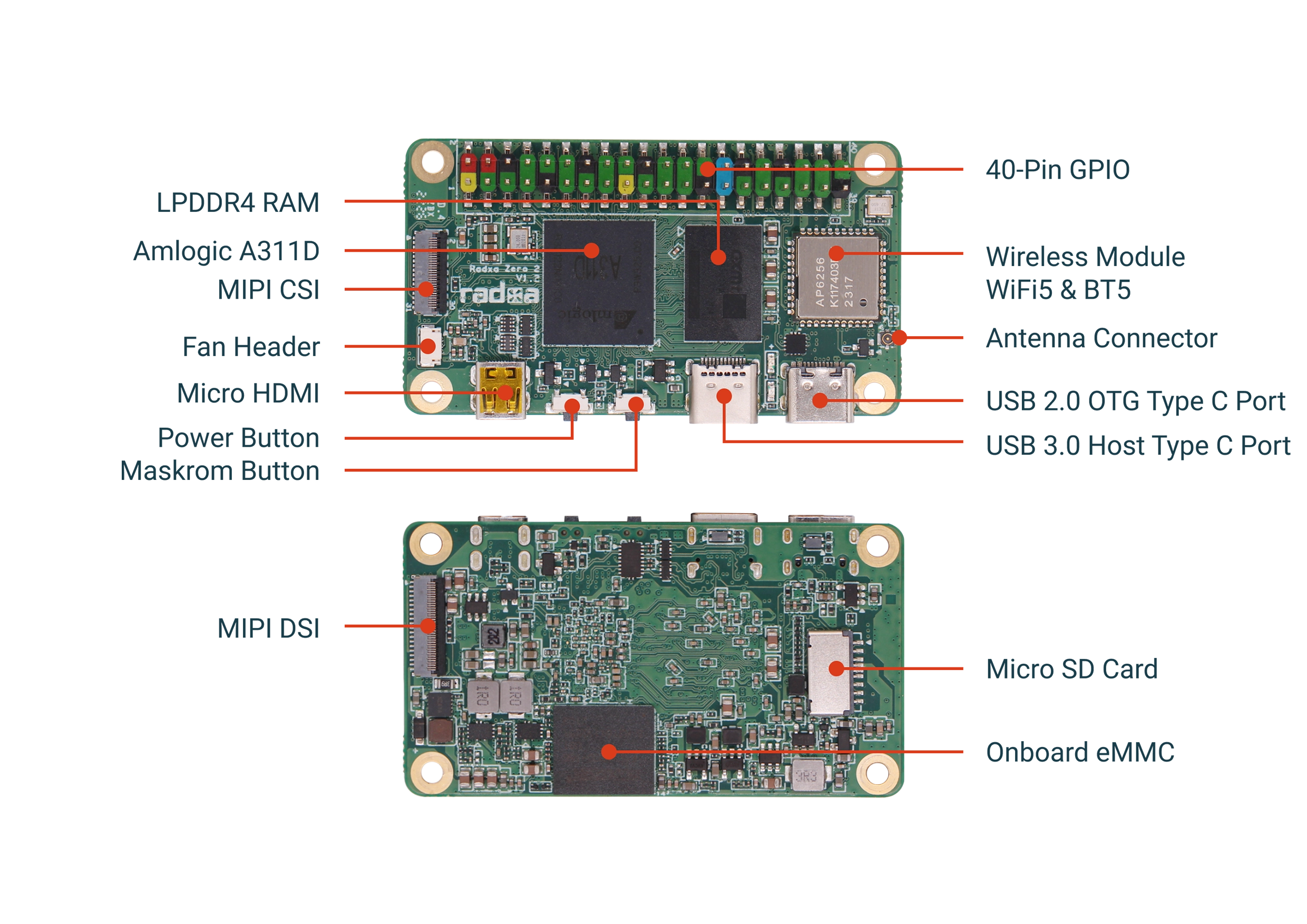
Interfaces Overview
- ZERO 2 PRO
USB OTG(Power Connection)
The ZERO 2 PRO is powered by a Type-C connector with an input voltage of 5V, and it is recommended to use a power adapter with a rated maximum current of more than 2A.
The official [Radxa Power PD 30W] is recommended (... /accessories/power/pd_30w). 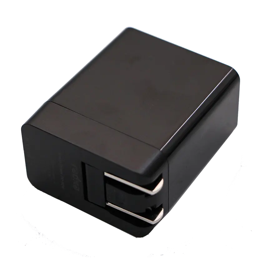
This interface can be used to connect peripherals such as keyboard, mouse, and USB flash drive.
TYPE-c USB3.0
This interface can be used to connect peripherals such as keyboards, mice, and USB flash drives.
40 PIN GPIO
GPIO voltage
| GPIO | Voltage | Max voltage |
|---|---|---|
| All GPIO | 3.3V | 3.3V |
GPIO Interface
The ZERO 2 PRO provides a 40 pin GPIO socket that is compatible with most SBC accessories on the market.
Hint: Actual compatibility is subject to usage.
| GPIO number | Function6 | Function5 | Function4 | Function3 | Function2 | Function1 | Pin# | Pin# | Function1 | Function2 | Function3 | Function4 | Function5 | Function5 | GPIO number |
|---|---|---|---|---|---|---|---|---|---|---|---|---|---|---|---|
| +3.3V | 1 | 2 | +5.0V | ||||||||||||
| 490 | I2C_EE_M3_SDA | WORLD_SYNC | GPIOA_14 | 3 | 4 | +5.0V | |||||||||
| 491 | I2C_EE_M3_SCL | IR_REMOTE_IN | GPIOA_15 | 5 | 6 | GND | |||||||||
| 429 | TDMC_DIN0 | TDMC_D0 | TSIN_B_VALID | PWM_D | GPIO_Z2 | 7 | 8 | GPIOAO_0 | UART_AO_A_TXD | 412 | |||||
| GND | 9 | 10 | GPIOAO_1 | UART_AO_A_RXD | 413 | ||||||||||
| 430 | TDMC_DIN1 | TDMC_D1 | TSIN_B_SOP | GPIO_Z3 | 11 | 12 | GPIOA_1 | TDMB_SCLK | TDMB_SLV_SCLK | 477 | |||||
| 431 | TDMC_DIN2 | TDMC_D2 | TSIN_B_DIN0 | GPIO_Z4 | 13 | 14 | GND | ||||||||
| 432 | TDMC_DIN3 | TDMC_D3 | TSIN_B_CLK | GPIO_Z5 | 15 | 16 | GPIOZ_8 | ETH_RGMII_TX_CLK | BT656_A_DIN4 | TSIN_B_DIN2 | MCLK_1 | I2C_EE_M0_SCL | 435 | ||
| +3.3V | 17 | 18 | GPIOZ_6 | TSIN_B_FAIL | TDMC_FS | TDMC_SLV_FS | 433 | ||||||||
| 447 | SPI_B_MOSI | UART_EE_C_RTS | GPIOH_4 | 19 | 20 | GND | |||||||||
| 448 | TDMB_DIN3 | TDMB_D3 | PWM_F | SPI_B_MISO | UART_EE_C_CTS | GPIOH_5 | 21 | 22 | GPIOZ_9 | ETH_TXEN | BT656_A_DIN5 | TSIN_B_DIN3 | 436 | ||
| 450 | PWM_B | I2C_EE_M1_SCL | SPI_B_SCLK | UART_EE_C_TX | GPIOH_7 | 23 | 24 | GPIOH_6 | UART_EE_C_RX | SPI_B_SS0 | I2C_EE_M1_SDA | IR_REMOTE_OUT | 449 | ||
| GND | 25 | 26 | SARADC_CH2 | ||||||||||||
| 427 | PWM_B | I2C_EE_M0_SDA | GPIOZ_0 | 27 | 28 | GPIOZ_1 | I2C_EE_M0_SCL | PWM_C | 428 | ||||||
| 419 | TDMB_SLV_FS | TDMB_FS | TSIN_A_DIN0 | GPIOAO_7 | 29 | 30 | GND | ||||||||
| 480 | PWM_D | TDMB_DIN1 | TDMB_D1 | GPIOA_4 | 31 | 32 | GPIOA_0 | MCLK_0 | 476 | ||||||
| 420 | TDMB_SLV_SCLK | TDMB_SCLK | TSIN_A_CLK | UART_AO_B_TX | GPIOAO_8 | 33 | 34 | GND | |||||||
| 478 | TDMB_SLV_FS | TDMB_FS | GPIOA_2 | 35 | 36 | GPIOA_3 | TDMB_D0 | TDMB_DIN0 | 479 | ||||||
| 421 | MCLK_0 | TSIN_A_VALID | UART_AO_B_RX | IR_REMOTE_OUT | GPIOAO_9 | 37 | 38 | GPIOA_5 | PDM_DIN3 | TDMB_DIN2 | TDMB_D2 | 481 | |||
| GND | 39 | 40 | GPIOZ_7 | I2C_EE_M0_SDA | TSIN_B_DIN1 | TDMC_SCLK | TDMC_SLV_SCLK | 434 |
MIPI DSI
| PIN | PIN definition |
|---|---|
| 1 | LCD_VCC |
| 2 | VDDIO_AO18 |
| 3 | NC |
| 4 | TDMB_D2 |
| 5 | NC |
| 6 | GND |
| 7 | MIPI_D0_N |
| 8 | MIPI_D0_P |
| 9 | GND |
| 10 | MIPI_D1_N |
| 11 | MIPI_D1_P |
| 12 | GND |
| 13 | MIPI_CLK_N |
| 14 | MIPI_CLK_P |
| 15 | GND |
| 16 | MIPI_D2_N |
| 17 | MIPI_D2_P |
| 18 | GND |
| 19 | MIPI_D3_N |
| 20 | MIPI_D3_P |
| 21 | GND |
| 22 | GND |
| 23 | TP_RESET |
| 24 | VCC3.3V |
| 25 | TOUCH_INT |
| 26 | TOUCH_I2C_SDA |
| 27 | TOUCH_I2C_SCL |
| 28 | GND |
| 29 | GND |
| 30 | LCD_VCC |
| 31 | LCD_VCC |
| 32 | GND |
| 33 | GND |
| 34 | VCC_LEDK |
| 35 | VCC_LEDK |
| 36 | NC |
| 37 | NC |
| 38 | VCC_LEDA |
| 39 | VCC_LEDA |
MIPI CSI
| PIN | PIN definition |
|---|---|
| 1 | GND |
| 2 | MIPI_CSI_D3N |
| 3 | MIPI_CSI_D3P |
| 4 | GND |
| 5 | MIPI_CSI_D2N |
| 6 | MIPI_CSI_D2P |
| 7 | GND |
| 8 | MIPI_CSI_CLKBN |
| 9 | MIPI_CSI_CLKBP |
| 10 | GND |
| 11 | MIPI_CSI_D1N |
| 12 | MIPI_CSI_D1P |
| 13 | GND |
| 14 | MIPI_CSI_D0N |
| 15 | MIPI_CSI_D0P |
| 16 | GND |
| 17 | MIPI_CSI_CLKAN |
| 18 | MIPI_CSI_CLKAP |
| 19 | GND |
| 20 | CM_MCLK |
| 21 | GND |
| 22 | CM_MCLK |
| 23 | CM_PWRDN_1 |
| 24 | CM_I2C_SCL |
| 25 | CM_I2C_SDA |
| 26 | CM_FS |
| 27 | CM_RST_L |
| 28 | VCC3.3V |
| 29 | VCC3.3V |
| 30 | VCC5V |
| 31 | VCC5V |
Micro HDMI
The Radxa ZERO 2 PRO has a micro HDMI video output port on board, which requires a micro HDMI to standard HDMI cable to connect to the monitor.
The resolution of the HDMI output depends on the monitor, and the Radxa ZERO 2 PRO will adjust to the optimal display resolution according to the monitor.
eMMC
On-board eMMC on the back of the Radxa Zero 2 Pro for eMMC booting or data storage.
WIFI/BT
ZERO 2 PRO has a Wi-Fi 5 (802.11 b/g/n/ac) & BT 5.0 with BLE wireless module on board.
microSD card slot
For microSD card boot or data storage.
Power button
For switching on/off
Maskrom Button
The ZERO 2 PRO supports Maskrom mode, which is a special mode of operation in which the CPU waits for commands from the USB OTG port. When you need to write image to eMMC, you need to use Maskrom button to enter Maskrom mode.
Fan Socket
| PIN | PIN definition |
|---|---|
| 1 | GND |
| 2 | GPIOAO-11 |
| 3 | VCC5V |