rsetup
rsetup
rsetup is a system configuration tool for Radxa OS.
To start rsetup, execute the rsetup command in a terminal, or find the rsetup application from the system menu:
rsetup requires administrator privileges to run. Please make sure you have sudo privilege.
The options listed below are for reference only and are subject to the actual program output.
┌──────────────────────────────────┤ RSETUP ├──────────────────────────────────┐
│ Please select an option below:                                               │
│                                                                              │
│                             System Maintenance                               │
│                             Hardware                                         │
│                             Overlays                                         │
│                             Connectivity                                     │
│                             User Settings                                    │
│                             Localization                                     │
│                             About                                            │
│                                                                              │
│                     <Ok>                         <Cancel>                    │
│                                                                              │
└──────────────────────────────────────────────────────────────────────────────┘
Interface Operation
Use the Up and Down keys to select between the menu options. The currently selected item is highlighted.
Use the Tab key to select between the menu area and the command area.
Use the Left and Right keys to toggle between the <Ok> and <Cancel> commands. Use the Enter key to execute the selected command.
Pressing the Enter key, when the command area is not selected, will immediately execute the <Ok> command.
Use the Space key to select items. Items are prefixed with [ ] (indicating multiple selections) or ( ) (indicating single selection) to show the current selection status.
Using the Enter key does not select any item. It executes the <Ok> command directly.
Use the Esc key to return to the previous menu.
System Maintenance
This menu contains the following options:
┌──────────────────────────────────┤ RSETUP ├──────────────────────────────────┐
│ System Maintenance                                                           │
│                                                                              │
│                         System Update                                        │
│                         Update Bootloader                                    │
│                         Update SPI Bootloader                                │
│                         Update eMMC Boot partition                           │
│                                                                              │
│                     <Ok>                         <Cancel>                    │
│                                                                              │
└──────────────────────────────────────────────────────────────────────────────┘
System Update
Do not use the apt-get upgrade command to update the system, as this will result in an incomplete update, which may lead to abnormal or missing functionality, or even a failure to boot the system.
You should use rsetup to update the system.
This option will update the packages installed on your system to the latest release.
Since RadxaOS provides some packages that conflict with the upstream Debian, it is recommended to update your system in this way to ensure system consistency.
Update Bootloader
This option updates the bootloader on the disk where the root file system is located.
Update SPI Bootloader
This option updates the bootloader on the SPI Flash.
Update eMMC Boot partition
This option updates the bootloader on the eMMC Boot partition.
Hardware
Some peripherals can be modified on this menu, the following is the introduction of them.
┌──────────────────────────────────┤ RSETUP ├──────────────────────────────────┐
│ Manage on-board hardware                                                     │
│                                                                              │
│                      Video capture devices                                   │
│                      GPIO LEDs                                               │
│                      Thermal governor                                        │
│                      Configure DSI display mirroring                         │
│                      USB OTG services                                        │
│                                                                              │
│                     <Ok>                         <Cancel>                    │
│                                                                              │
└──────────────────────────────────────────────────────────────────────────────┘
Video capture devices
If you have connect a video device, this option can help you to capture an image for testing.
GPIO LEDs
On this option, you can change the status of power LED and user LED on the board (Sometimes only one).
LED Setup
LED Setup
Some products will have user-controllable LEDs on-board. They can be managed via rsetup:
┌──────────────────────────────────┤ RSETUP ├──────────────────────────────────┐
| Below are the available LEDs and their triggers.                             |
| Select any to update their trigger.                                          |
|                                                                              |
|    [ ] user-led1 [default-on]                                                |
|    [ ] user-led2 [heartbeat]                                                 |
|                                                                              |
|                     <Ok>                         <Cancel>                    |
|                                                                              |
└──────────────────────────────────────────────────────────────────────────────┘
The content inside '[ ]' at the end is the current LED trigger, which can be roughly understood as the LED status.
On Radxa products, the power LED usually has default-on trigger, while the status LED usually has heartbeat trigger.
Change LED light status
The following steps help us to change light status:
- Use the
upordownkey to move the highlighted selection to which LED you want to edit the status; - Use the
Spacebar to confirm your choose, a*would appeare on the[ ]at the start.
┌──────────────────────────────────┤ RSETUP ├──────────────────────────────────┐
| Below are the available LEDs and their triggers.                             |
| Select any to update their trigger.                                          |
|                                                                              |
|    [*] user-led1 [default-on]                                                |
|    [ ] user-led2 [heartbeat]                                                 |
|                                                                              |
|                     <Ok>                         <Cancel>                    |
|                                                                              |
└──────────────────────────────────────────────────────────────────────────────┘
- Press
Enterto go to the trigger selection menu:
┌──────────────────────────────────┤ RSETUP ├──────────────────────────────────┐
│ Please select the new trigger:                                               │
│                                                                              │
│    ( ) none                                                                  │
│    ( ) rfkill-any                                                            │
│    ( ) rfkill-none                                                       ▒   │
│    ( ) kbd-scrolllock                                                    ▒   │
│    ( ) kbd-numlock                                                       ▒   │
│    ( ) kbd-capslock                                                      ▒   │
│    ( ) kbd-kanalock                                                      ▒   │
│    ( ) kbd-shiftlock                                                     ▒   │
│    ( ) kbd-altgrlock                                                     ▒   │
│    ( ) kbd-ctrllock                                                      ▒   │
│    ( ) kbd-altlock                                                       ▒   │
│    ( ) kbd-shiftllock                                                    ▒   │
│    ( ) kbd-shiftrlock                                                    ▒   │
│    ( ) kbd-ctrlllock                                                     ▒   │
│    ( ) kbd-ctrlrlock                                                     ▒   │
│    ( ) disk-activity                                                         │
│             (and more)                                                       │
│                                                                              │
│                     <Ok>                         <Cancel>                    │
│                                                                              │
└──────────────────────────────────────────────────────────────────────────────┘
- Use the
upanddownarrow keys to select which you like and pressSpaceto confirm, a*would appeare on the( )like step 2. - Press
Enterto save your choose and apply it. - Your LED status would change after step 5 at once.
Thermal governor
This module is used to adjust the fan and other temperature options.
Generally, we select power_allocator when using DC fan or fanless, select step_wise when using PWM fan.
Note: If you connect the fan directly to the GPIO on 5V and GND pins, it would not be controlled and always work.
Configure DSI display mirroring
If DSI display has some problems when using HDMI display and DSI display at the same time, enable this option will helpful.
USB OTG services
Enabling Device function configuration for the OTG port:
# `*.*` is the corresponding USB controller

radxa-adbd@*.*  # Configured as an ADB device
radxa-ecm@*.*   # Configured as an ECM device (not recommended)
radxa-ncm@*.*   # Configured as an NCM device (recommended)
Overlays
This option is for Configure Device Tree Overlay.
Device Tree Configuration
Device tree settings
Device Tree Overlays make it possible to support multiple hardware configurations with a single kernel, without explicitly loading or masking kernel modules.
You can use rsetup to manage overlays.
How to Enable an Overlay
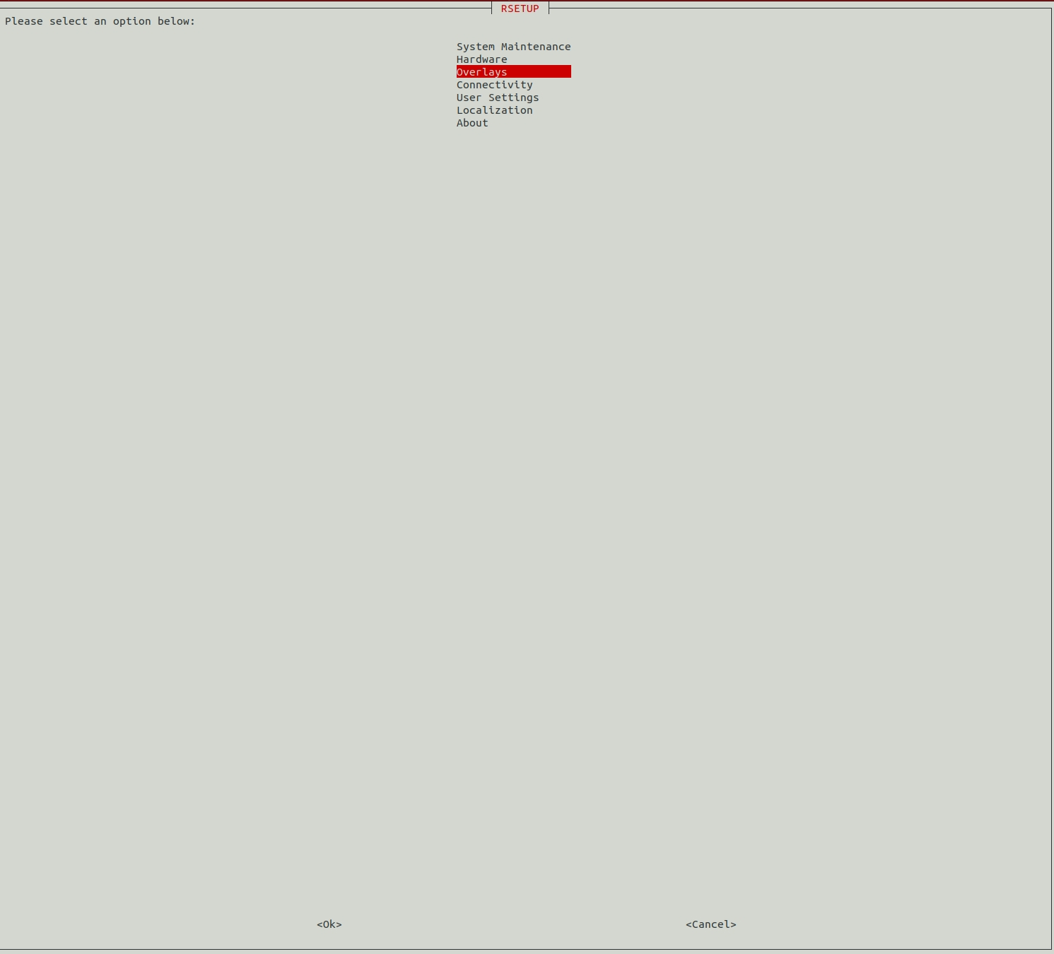
In the screen of rsetup, use the arrow keys to move up, down, left, right, and select.
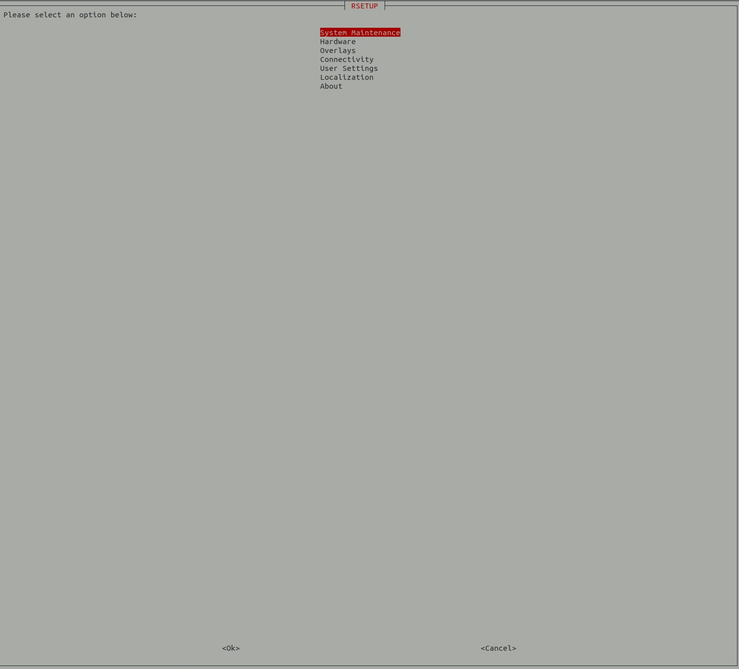
Select the third item Overlays:
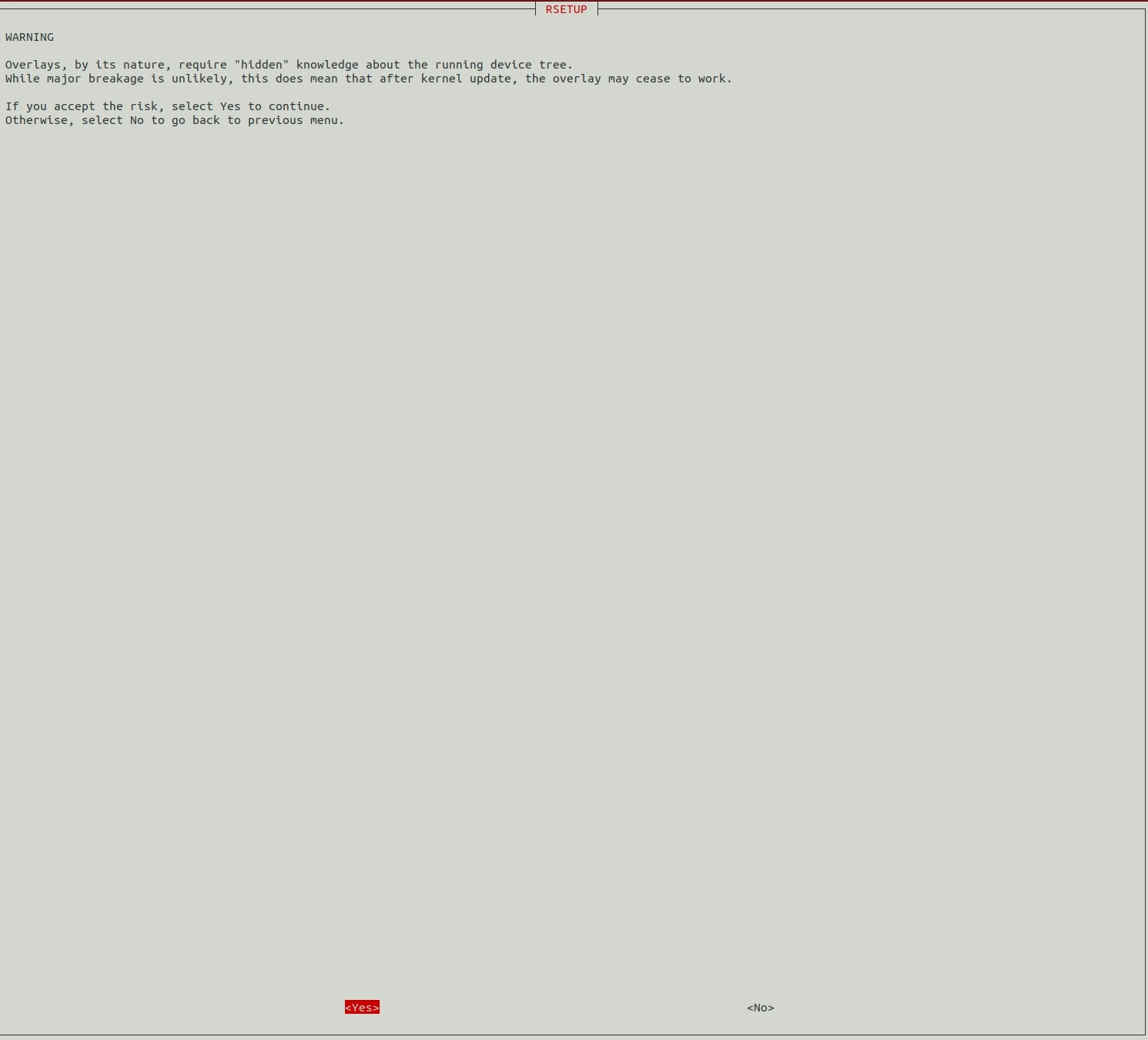
Select Yes.
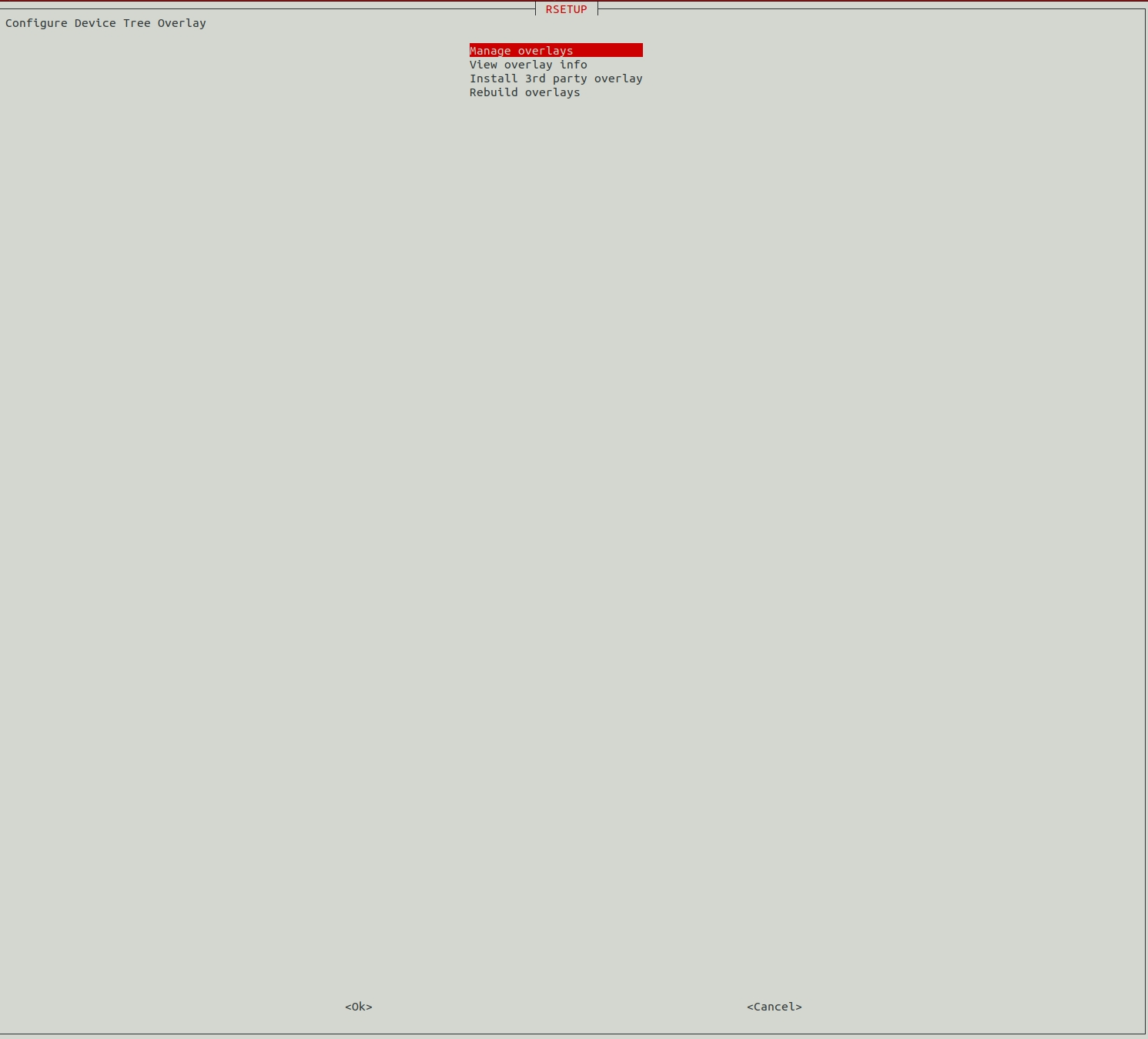
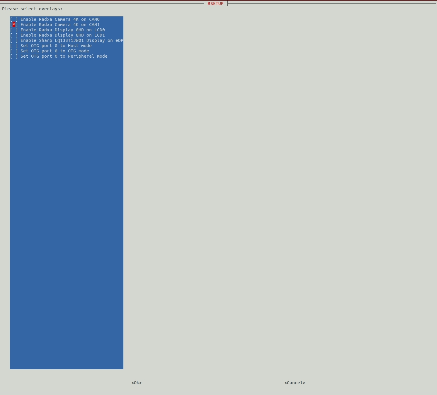
Select Manage overlays,
Press the spacebar to select the Overlay you want, a * mark when selected means it is enabled.
Here is the example of ROCK 5 ITX, different products will have different Overlay.
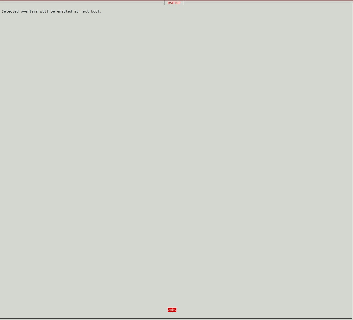
Select Yes, Overlay needs to be restarted to take effect.
Press ESC until you exit rsetup.
Install 3rd party overlay
Install 3rd party overlay
Device Tree Overlays make it possible to support many hardware configurations with a single kernel and without the need to explicitly load or blacklist kernel modules.
You can use rsetup to manage overlays.
The Install 3rd party overlay feature of rsetup installs both device tree overlay files (DTBO) and source code (DTS).
Pre-compiled files from the official DTBO repository radxa/overlays can be downloaded from here.
Get radxa/overlays source code
git clone https://github.com/radxa/overlays.git
cd overlays
Load the overlay using rsetup
Select Overlays in rsetup's main interface:
Configure Device Tree Overlay
        Manage overlays
        View overlay info
        Install 3rd party overlay"
        Reset overlays
        <Ok>             <Cancel>
Then, select Install 3rd party overlay:
Configure Device Tree Overlay
        Manage overlays
        View overlay info
        Install 3rd party overlay
        Reset overlays


      <Ok>            <Cancel>
The following is the path to the source code of the Rexchip SOC device tree overlay file.
arch/arm64/boot/dts/rockchip/overlays/*.dts
If the SOC vendor is Amlogic, you need to replace rockchip with amlogic in the above path.
Then select the overlay you want to load, then exit rsetup, and finally reboot.
You can check the parameters using cat /boot/extlinux/extlinux.conf
Adding LEDs
Add LED
Single board computers or computing modules shipped by Radxa usually have two LEDs by default: One power light (not modifiable by software) and a system heartbeat light. If you want to have a hard disk status light or a network port status light like a PC, follow the tutorial! Using the Radxa 5B as an example, you need to modify the device tree overlay file (DTBO) according to the GPIOs used.
- Hardware connections
GPIO3_C1(PIN11)(3.3V) <----> Resistor (select size according to LED datasheet) <----> LED positive <----> LED Negative <----> GND(PIN9)
- Edit device tree overlay file (DTBO)
nano ~/user_led3.dts
The following is the content of the DTBO:
The triggers that can be used: none rc-feedback rfkill-any rfkill-none kbd-scrolllock kbd-numlock kbd-capslock kbd-kanalock kbd-shiftlock kbd-altgrlock kbd-ctrllock kbd-altlock kbd-shiftllock kbd-shiftrlock kbd-ctrlllock kbd-ctrlrlock tcpm-source-psy-4-0022-online disk-activity disk-read disk-write ide-disk mtd nand-disk cpu cpu0 cpu1 cpu2 cpu3 cpu4 cpu5 cpu6 cpu7 panic mmc2 mmc1 mmc0 default-on heartbeat pattern timer rfkill1 phy0rx phy0tx phy0assoc phy0radio rfkill2 rfkill3
/dts-v1/;
/plugin/;

#include <dt-bindings/gpio/gpio.h>
#include <dt-bindings/pinctrl/rockchip.h>

/ {
    fragment@0 {
        target-path = "/";                                      /* Primary dts node to be modified */
        __overlay__ {                                           /* Add or modify the contents of these brackets */
            custom-leds{                                        /* Add custom-leds node */
                compatible = "gpio-leds";
                status = "okay";
                microsd-led {                                   /* Add icrosd-led node */
                    gpios = <&gpio3 RK_PC1 GPIO_ACTIVE_HIGH>;   /* Register GPIO3_C1 as the enable pin of microsd-led, the enable is level-pull-high by default. */
                    linux,default-trigger = "mmc1";             /* Set default trigger to mmc1(SD Card) */
                };
            };
        };
    };
};
- Load the DTBO
rsetup

# Follow these options to access the Install 3rd party overlay interface
# Overlays -> Install 3rd party overlay
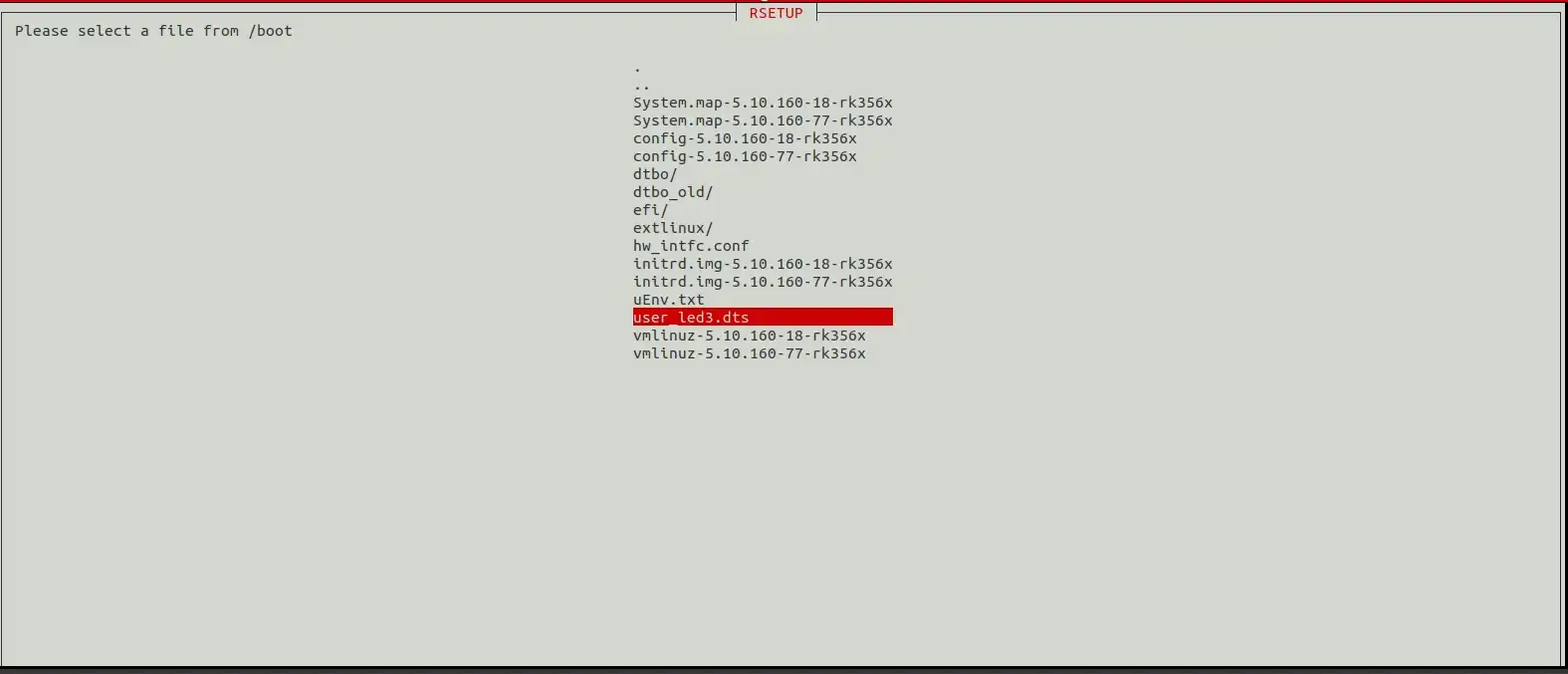
- Select user_led3.dts
- Reboot
sudo reboot
After reboot, you can see the LEDs flashing to follow the status of the hard disk.
Configure Pins 8 and 10 as GPIOs
Configure Pins 8 and 10 as GPIOs
By default, the UART2_M0 interface is a FIQ debugging serial port, which can output logs of DDR Init, U-Boot, Linux Kernel, etc. for debugging. Therefore, it is not recommended to cancel this configuration as you can use other serial ports if not necessary.
- Disable the FIQ-Debugger configuration.
rsetup

# Follow these options to access the Manage overlays interface
# Overlays -> Manage overlays
Tick Disable FIQ Debugger.
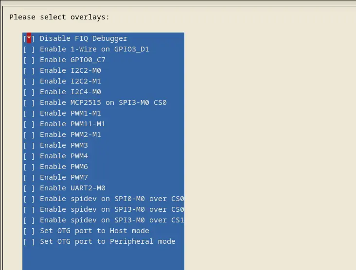
Check the box and select OK, then exit rsetup and reboot the system, PIN 8 && PIN 10 can be used as normal GPIOs.
Configure UART2_M0 as normal serial port
Configure UART2_M0 as normal serial port
By default, the UART2_M0 interface is a FIQ debugging serial port, which can output logs of DDR Init, U-Boot, Linux Kernel and other logs for debugging. Therefore, it is not recommended to cancel this configuration as you can use other serial ports if not necessary.
- Enable UART2_M0
rsetup

# Follow these options to access the Manage overlays interface
# Overlays -> Manage overlays
Tick Enable UART2-M0
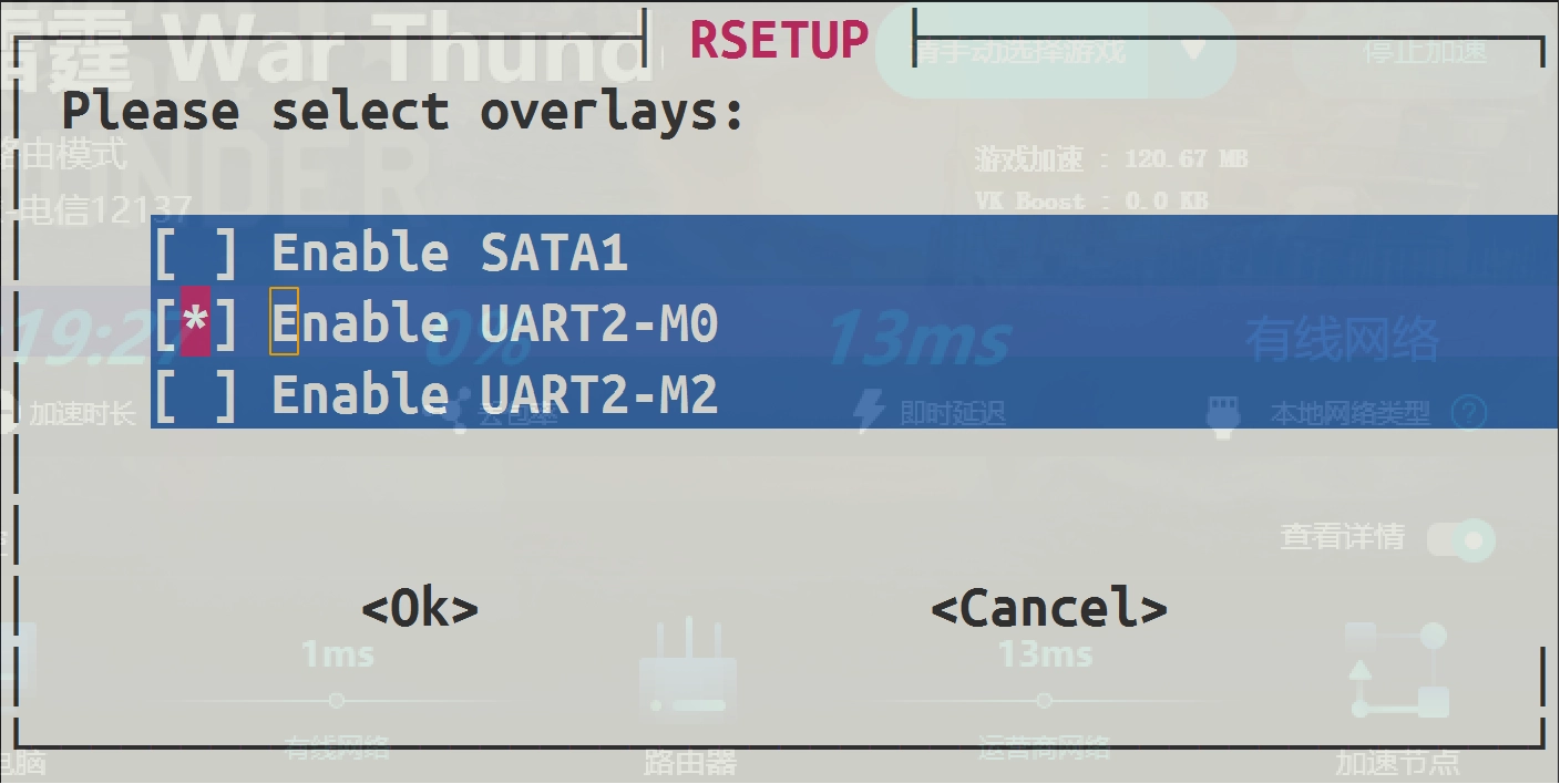
Select OK, then exit rsetup.
- Modify Linux boot parameters
Following Linux boot parameters, remove all ttyFIQ0 and ttyS2 related console parameters from the /etc/kernel/cmdline file, e.g. "console=ttyFIQ0,1500000n8".
Connectivity
This option is normally similar to network setting.
User Settings
Password
Changes the password of the current user.
Hostname
Modify the current hostname.
Configure auto login
If the rsetup option does not show Configure auto login, please use the System -> System Update option in the rsetup tool to update and restart the system.
Configure auto login for TTY Terminal and Desktop Manager.
Localization
On this option, you can change Timezone Locale Keybaed layout Wi-Fi Country.
About
Here is the information of rsetup.