Install BIOS
If you are using RadxaOS, the system provides built-in functionality for updating the BIOS, so you don't need to follow the manual update instructions below.
Simply select the Install EDK2 boot option during startup and follow the on-screen instructions to confirm the operation.
You can also install RadxaOS on a USB storage device and use it as a BIOS update medium for multiple devices.
For more details, please refer to the edk2-cix documentation.
Hardware Requirements
- Motherboard: Radxa Orion O6
- Power Adapter: 20V Type-C Power Adapter
- For Creating BIOS USB Drive: USB flash drive
- Input Device: USB Keyboard
- USB-to-Serial Cable (Optional): For serial debugging and system login
- HDMI Cable and Monitor (Optional): For displaying the system interface and graphical operations
Recommended Accessories:
Hardware Specifications
The Orion O6 motherboard supports standard PD protocol with 20V power input. A current of 3A or higher is recommended to ensure stable operation of all peripherals.
- USB Flash Drive
Used to create a BIOS USB drive. There are no strict capacity requirements, as the extracted BIOS package is approximately 10MB in size.
- USB-to-Serial Cable
Used to connect the Orion O6 to a PC when updating the BIOS in command-line mode.
- HDMI Cable and Monitor
Used to connect the Orion O6 to a monitor when updating the BIOS in display mode.
Creating a BIOS USB Drive
Download the BIOS Package
Go to the Download Page to download the files needed to create a BIOS USB drive and extract them.
The extracted files should include:
BuildOptions
BurnImage.efi
cix_flash_all.bin
cix_flash_ota.bin
FlashUpdate.efi
startup.nsh
Shell.efi
VariableInfo.efi
Create the BIOS USB Drive
-
Format your USB drive with a single FAT32 partition.
-
Copy all the extracted BIOS files to the root directory of the FAT32 partition on your USB drive.
This completes the creation of the BIOS USB drive.
Updating the BIOS
This section describes how to update the BIOS using either the display mode or serial port mode.
Hardware Connections
- Display Mode
- Serial Mode
- Connect a USB keyboard to the Orion O6
- Connect a monitor to the Orion O6 using an HDMI cable
- Connect the Orion O6 to a 20V Type-C power adapter
- Connect the Orion O6's 3-pin UART2 header to your PC's USB port using a USB-to-serial cable
- Connect a USB keyboard to the Orion O6
- Connect the Orion O6 to a 20V Type-C power adapter
Baud Rate: 115200
Data Bits: 8
Stop Bits: 1
Parity: None
Flow Control: None
You can use any serial terminal application of your choice. We recommend using Tabby.
- Serial Connection Diagram
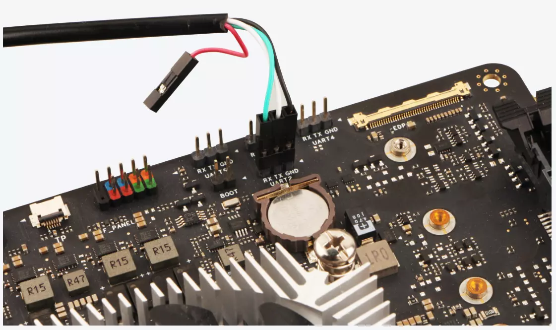
| Orion O6 Pin Function | Connection |
|---|---|
| Orion O6 : GND | GND pin of USB-to-serial cable (black jumper wire) |
| Orion O6 : UART2_TXD | RXD pin of USB-to-serial cable (white jumper wire) |
| Orion O6 : UART2_RXD | TXD pin of USB-to-serial cable (green jumper wire) |
Entering BIOS
- Display Mode
- Serial Mode
After powering on, when you see the Radxa logo and progress bar on the monitor, briefly press the "Esc" key to bring up the BIOS menu.
After powering on, if you see Press ESCAPE for boot options in the serial output, press the ESC key to enter the BIOS menu.
Tianocore/EDK2 firmware version 0.3.0-1
Press ESCAPE for boot options
- BIOS Interface
 Radxa Orion O6
 CIX P1 CD8180                                       1.50 GHz
 0.3.0-1                                             8192 MB RAM


   Select Language            <English>                  This is the option
                                                         one adjusts to change
 > Device Manager                                        the language for the
 > Boot Manager                                          current system
 > Boot Maintenance Manager

   Continue
   Reset


  ^v=Move Highlight       <Enter>=Select Entry
Updating the BIOS
In the BIOS interface, select Boot Manager --> UEFI Shell to enter the UEFI Shell interface.
You can press q to cancel the automatic BIOS update and exit the tool. To update the BIOS, you'll need to access the specified disk and run the startup.nsh script file.
UEFI Interactive Shell v2.2
EDK II
UEFI v2.70 (EDK II, 0x00010000)
Mapping table
      FS0: Alias(s):HD0b0b:;BLK1:
          VenHw(0D51905B-B77E-452A-A2C0-ECA0CC8D514A,00801E090000000000)/USB(0x1
,0x0)/HD(1,GPT,40EC1CE6-AF3E-4B61-9E8F-29906C777ACE,0x12000,0x73DB800)
     BLK0: Alias(s):
          VenHw(0D51905B-B77E-452A-A2C0-ECA0CC8D514A,00801E090000000000)/USB(0x1
,0x0)
Press ESC in 1 seconds to skip startup.nsh or any other key to continue.
************************************************************************
                       Radxa BIOS Update Utility
************************************************************************

You are about to update the BIOS.
Please make sure the power stays on during the operation.

If you decide to cancel BIOS update, you can run following commands:
    reset     to reboot the system
    reset -s  to shutdown the system

Enter 'q' to quit, any other key to continue:
q
- Accessing the BIOS Directory
In the Shell, type FS0: and press Enter to access the BIOS USB drive. Then use the ls command to verify that the files are in the directory.
You can identify your BIOS USB drive information from the Mapping table above. In our case, the device is identified as FS0.
Shell> FS0:
FS0:\> ls
Directory of: FS0:\
04/28/2025  03:28                 649  BuildOptions
04/28/2025  03:28              57,344  BurnImage.efi
04/28/2025  03:28           6,288,062  cix_flash_all.bin
04/28/2025  03:28           2,101,982  cix_flash_ota.bin
04/28/2025  03:28             434,176  FlashUpdate.efi
04/28/2025  03:28             970,752  Shell.efi
04/28/2025  03:28               1,354  startup.nsh
04/28/2025  03:28              16,384  VariableInfo.efi
          8 File(s)   9,870,703 bytes
          0 Dir(s)
- Updating the BIOS
In the Shell, type startup.nsh and press Enter to update the BIOS.
If the downloaded BIOS package is from a version earlier than 0.3.0-1, the file will be named setup.nsh.
FS0:\> startup.nsh
After running startup.nsh, follow the on-screen prompts to complete the remaining BIOS update process.
If the update is successful, the system will display the following information:
************************************************************************
                       Radxa BIOS Update Utility
************************************************************************

You are about to update the BIOS.
Please make sure the power stays on during the operation.

If you decide to cancel BIOS update, you can run following commands:
    reset     to reboot the system
    reset -s  to shutdown the system

Enter 'q' to quit, any other key to continue:

************************************************************************
                            Updating BIOS...
************************************************************************

========================================================================
 Copyright 2024 Cix Technology Group Co., Ltd. All Rights Reserved.
                   FlashUpdate Utility v1.04.
                   Build Date:Mar 24 2025
========================================================================
Old Version:0.3.0-1
New Version:0.3.0-1
[00.17] Processing...
Flash update success.

************************************************************************
                         BIOS Update completed!
************************************************************************
System will now power off.
You MUST fully remove all connected power source before connecting them.
Failure to do so may prevent some components to use the updated code.

Enter 'q' to quit, any other key to continue:

Reset with BIOS Update (24 bytes)
Updating BIOS Firmware Using a Programmer
For advanced users who need to recover from a corrupted BIOS or prefer direct hardware access, you can use a Serial Flash programmer (such as CH341A) to directly flash the BIOS firmware (cix_flash_all.bin) to the SPI NOR Flash chip. This method completely bypasses the operating system and works even when the device cannot boot.
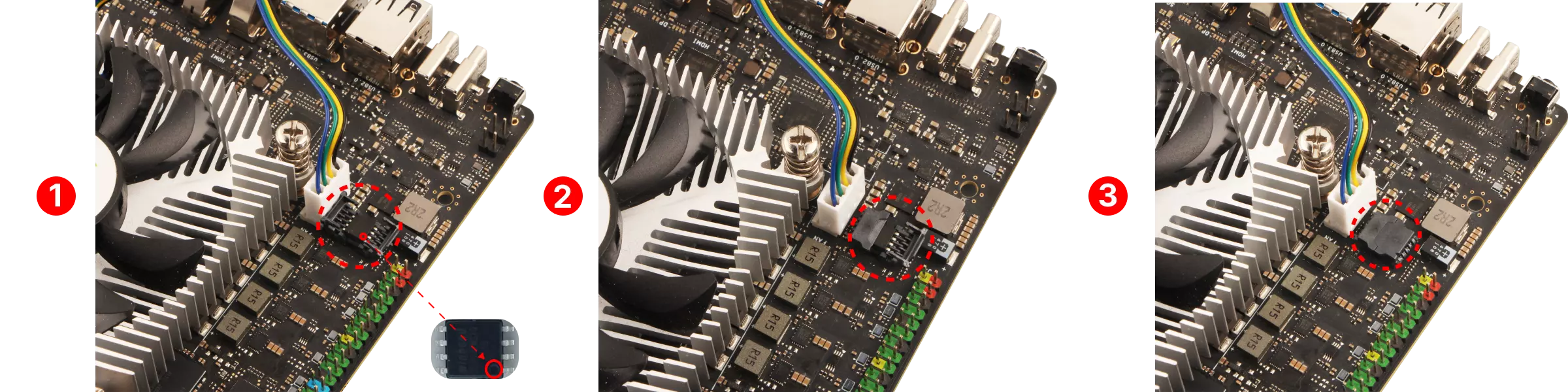
Removing the SPI Flash Chip
Steps to remove the SPI Flash chip:
① Locate the SPI Flash chip on the motherboard
② Open the right latch cover of the SPI Flash
③ Open the left latch cover of the SPI Flash
After completing the above steps, use tweezers to carefully remove the SPI Flash chip from the motherboard.
Flashing the BIOS Firmware
For detailed instructions and hardware requirements, please refer to the comprehensive forum guide provided by community member Meco.
The cix_flash_all.bin file required for the forum guide is included in the downloaded BIOS package.
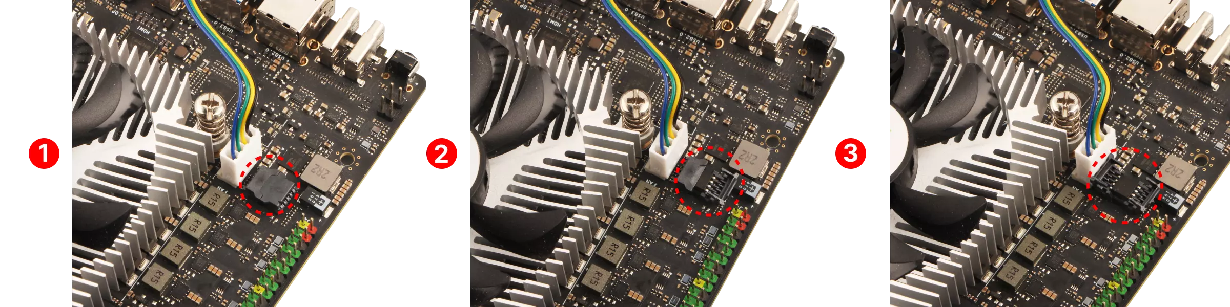
Installing the SPI Flash Chip
① Install the SPI Flash chip onto the motherboard
② Reattach the left latch cover of the SPI Flash
③ Reattach the right latch cover of the SPI Flash
- The circle on the chip indicates pin 1, which is marked with a small red circle in the image.
- The SPI Flash socket has a triangular arrow that corresponds to pin 1 of the SPI Flash.
You can use these two methods to confirm the correct orientation and position of the SPI Flash.