Hardware Interface Description
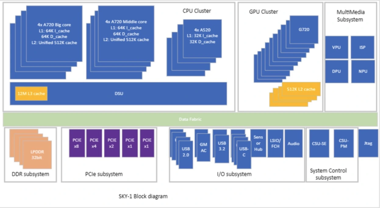
SoC Block Diagram
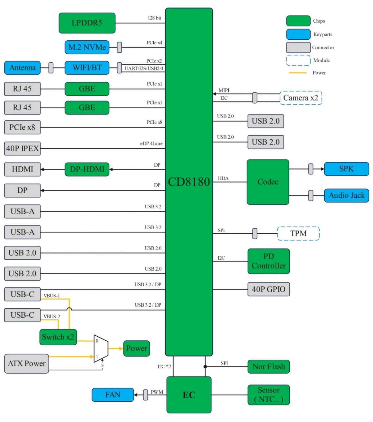
System Block Diagram
Board Layout
The detailed layout of the O6 motherboard, with numbered labels, is as follows:
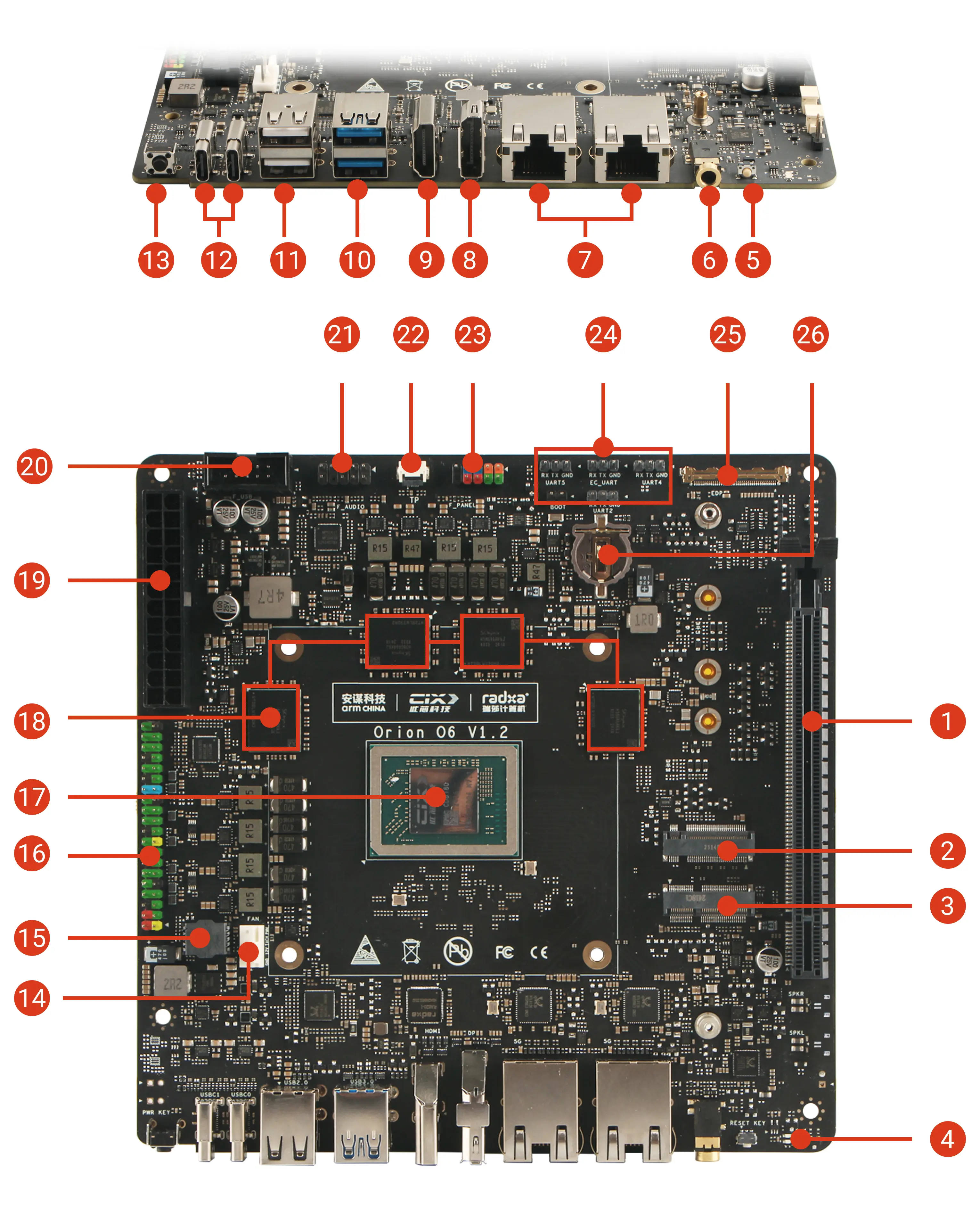
Component List
Back Panel
Power Button ⑬
The O6 board includes a dedicated power button for manual power control.
- When the OS is running: Short press the power button to trigger a power event. Depending on the OS settings, this action may display the power menu, initiate a shutdown, or put the system into suspend mode.
- When the OS is powered of: Short press the power button to power on the board.
- Long press (4 seconds): Forces the board to power off.
USB-C Ports ⑫
The dual USB‑C ports on the O6 support USB 3.2 Gen 2 (10Gbps), DP Alt Mode (4K@60Hz), and Power Delivery (PD).
-
A 65W PD power supply(20V / 3.25A) is recommended for powering the O6 from the USB‑C port.
-
Either USB‑C port can power the board. If two power sources are connected simultaneously (e.g., when using two USB‑C monitors with PD capability), the first plugged‑in PD source will supply power to the board.
-
Each USB‑C port can deliver up to 3A to power external USB‑C devices.
Double USB 2.0 ⑪
The double‑layer USB 2.0 host ports provide standard USB support. The combined current limit for the two ports is 1.4A.
Double USB 3.2 ⑩
The dual USB 3.2 host ports on the O6 provide SuperSpeed USB (10Gbps). Each port has a current limit of 1A.
HDMI ⑨
The HDMI Type‑A port on the O6 supports a maximum resolution of 4K@60Hz. Note that HDMI CEC is not supported.
DP ⑧
The DisplayPort (DP) on the O6 supports a maximum resolution of 4K@120Hz and offers 2x MST (Multi‑Stream Transport) capability.
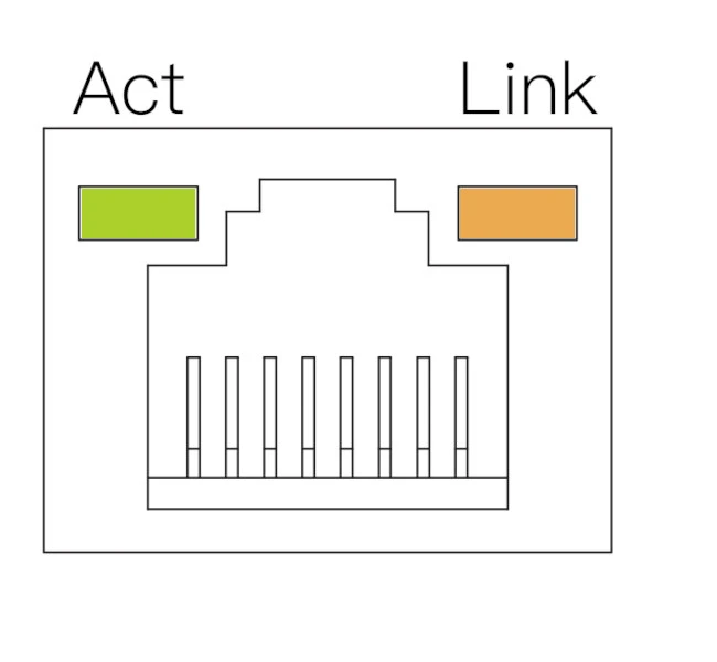
Double 5GbE ⑦
The dual Ethernet ports provide a wired connection with speeds up to 5Gbps. The LED indicators for these ports are described below:
 |
|
Headphone Jack ⑥
The 3.5mm headphone jack on the O6 supports both audio input and output. It can drive standard headphones and is compatible with commonly used ring configurations.
Reset Button ⑤
The O6 is equipped with a reset button for system resets. A short press will reboot the system.
Internal Components
CPU - Cix CD8180 ⑰
The CPU on the O6 board, the Cix CD8180, is soldered directly onto the board and is non‑replaceable.
DRAM ⑱
The DRAM on the O6 is soldered onto the board and is non‑replaceable. It consists of four 32‑bit LPDDR5 chips combined into a 128‑bit memory bus, achieving speeds of up to 5500 MT/s, with a total bandwidth of 0 GB/s.
PCIe X16 Slot ①
The O6 features a full‑size PCIe X16 slot, supporting PCIe Gen4 x8 signals. PCIe bifurcation is not supported for this port.
- Power supply:
- With ATX power: Maximum power from the PCIe slot is 60W.
- With USB-C PD power: Maximum power from the PCIe slot is 15W.
M.2 M Key ②
An M.2 M Key connector is provided on the O6, supporting 2230, 2242, 2260, and 2280 SSD types. The connector offers PCIe Gen4 x4 signals.
- Power supply:
- Constant power: 15W
- Peak power: 28W
M.2 E Key ③
A M.2 E Key connector is provided on O6, with 2230 WiFi / BT card support. PCIe Gen4 x2 and USB 2.0 signal is available from the connector. Constant 15W peak 28W powed is supplied from this connector.
on board LED ④
Two LEDs are included on the O6 board:
- Green LED:Indicates power status.
- Blue LED:Indicates system status.
- When the BIOS is running, the Blue LED remains on.
- When the OS is running, the Blue LED blinks to represent the system heartbeat.
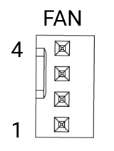
Fan Connector ⑭
The O6 features a standard ATX fan connector. The pinout is defined as follows:
 |
|
F_Panel Connector Pinout
BIOS Flash chip Holder ⑮
The O6 board includes a BIOS flash chip holder designed for developers to easily remove or replace the BIOS chip.
- Chip compatibility:Supports SOP8 footprint flash chips.
- Chip capacity:8MB(64Mbit)。
- Voltage level:1.8V。
This feature facilitates firmware development and debugging by allowing convenient BIOS chip replacement.
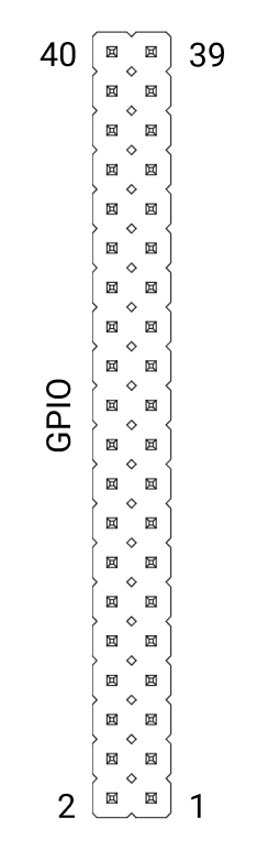
40Pin GPIO Connector ⑯
A 40‑pin GPIO connector is included on the O6 board, designed for low‑speed bus connections and general‑purpose input/output (GPIO) functionality.
 |
|
40Pin GPIO Pinout
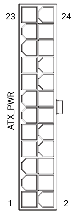
ATX Power Connector ⑲
An ATX‑compatible 24‑pin power connector is included on the O6 board for standard ATX power supply compatibility.
 |
|
ATX Power Connector Pinout
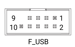
F_USB Connector ⑳
The F_USB connector is designed to support the front panel USB functionality of a PC enclosure. The pinout configuration is as follows:
 |
|
F_USB Connector Pinout
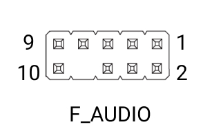
F_Audio Connector ㉑
The F_Audio connector is designed to support the front panel audio functionality of a PC enclosure. The pinout configuration is as follows:
 |
|
F_Audio Connector Pinout
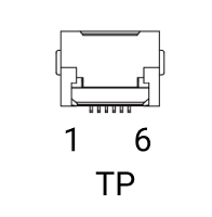
TP Connector ㉒
A touch panel connector is included on the O6 board to enable touch panel integration. Combined with the eDP connector, it provides a direct interface for connecting a touchscreen.
 |
|
Touch Panel Connector Pinout
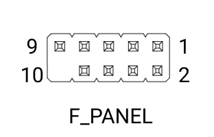
F_Panel Connector ㉓
The F_Panel connector is designed to support the front panel power button, reset button, and LED functionality of a PC enclosure. The pinout configuration is as follows:
 |
|
F_Panel Connector Pinout
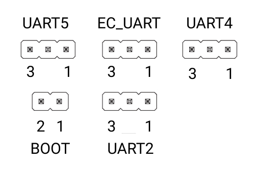
Debug Connectors ㉔
Four dedicated UART interfaces are included on the O6 board for various debugging purposes. Additionally, an EC UART is provided for the EC serial console.
- UART2:BIOS and OS debug logs
- UART4:Power management, voltage, and frequency monitoring
- UART5:Secure BootROM debug logs
- EC UART:On board Embedded Controller debug logs
The UART pinout configuration is as follows:
 |
|
| |||||||||||||||||||||||||||
Debug Connector Pinout
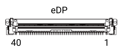
eDP Connector ㉕
A 40‑pin eDP connector is included on the O6 board to enable direct connection to eDP panels, supporting resolutions up to 4K@60Hz. The connector uses an IPEX 40‑pin, 0.5mm pitch design. The eDP connector provides a maximum power output of 12V / 2A.
 |
|
eDP Connector Pinout
RTC Battery Holder ㉖
The RTC battery holder on the O6 is designed for a CR1220 battery, which provides timekeeping functionality. Note that removing the RTC battery will not clear the BIOS settings.