Maskrom Mode
The ROCK 3C supports Maskrom mode, which is a special operation mode where the CPU receives commands through the USB OTG port. This guide will instruct you how to operate the ROCK 3C in Maskrom mode.
Preparation
- ROCK 3C SBC
- Type-C power adapter
- USB-A to USB-A adapter cable
- Male-to-male DuPont cable or other wire
- eMMC module or microSD card (optional)
Steps
-
Install the development tool
- Windows
- Linux_MacOS
Use RKDevTool for Windows, please refer to RKDevTool Guide for installation and tutorial.
For Linux and MacOS, you can use rkdeveloptool and upgrade_tool.
Please refer to rkdeveloptool guide and upgrade_tool guide for installation and tutorial. -
Remove eMMC module microSD card etc.
-
Connect one port of the USB-A to USB-A cable to the host port and the other port to the OTG port of the ROCK 3C (which is located on top of the USB 3.0 port), as shown below
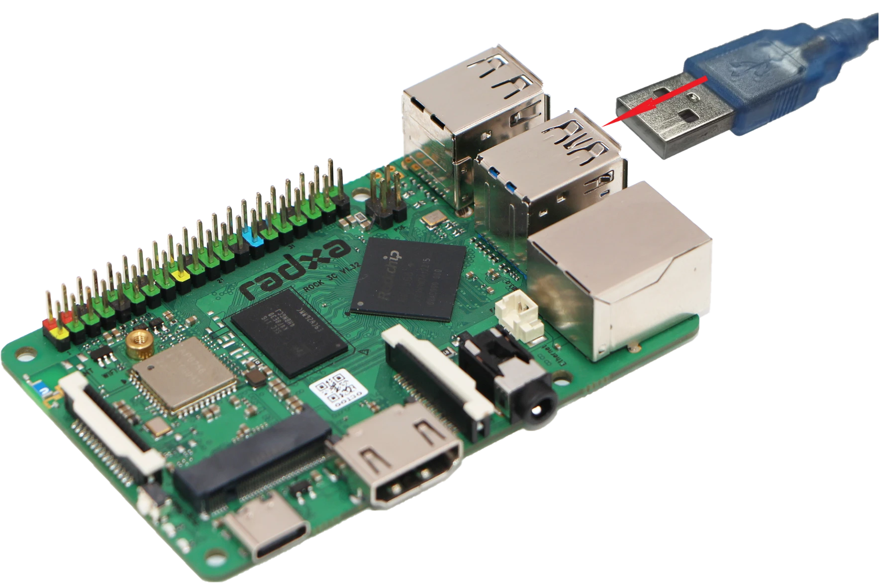
-
Connect the SPI port
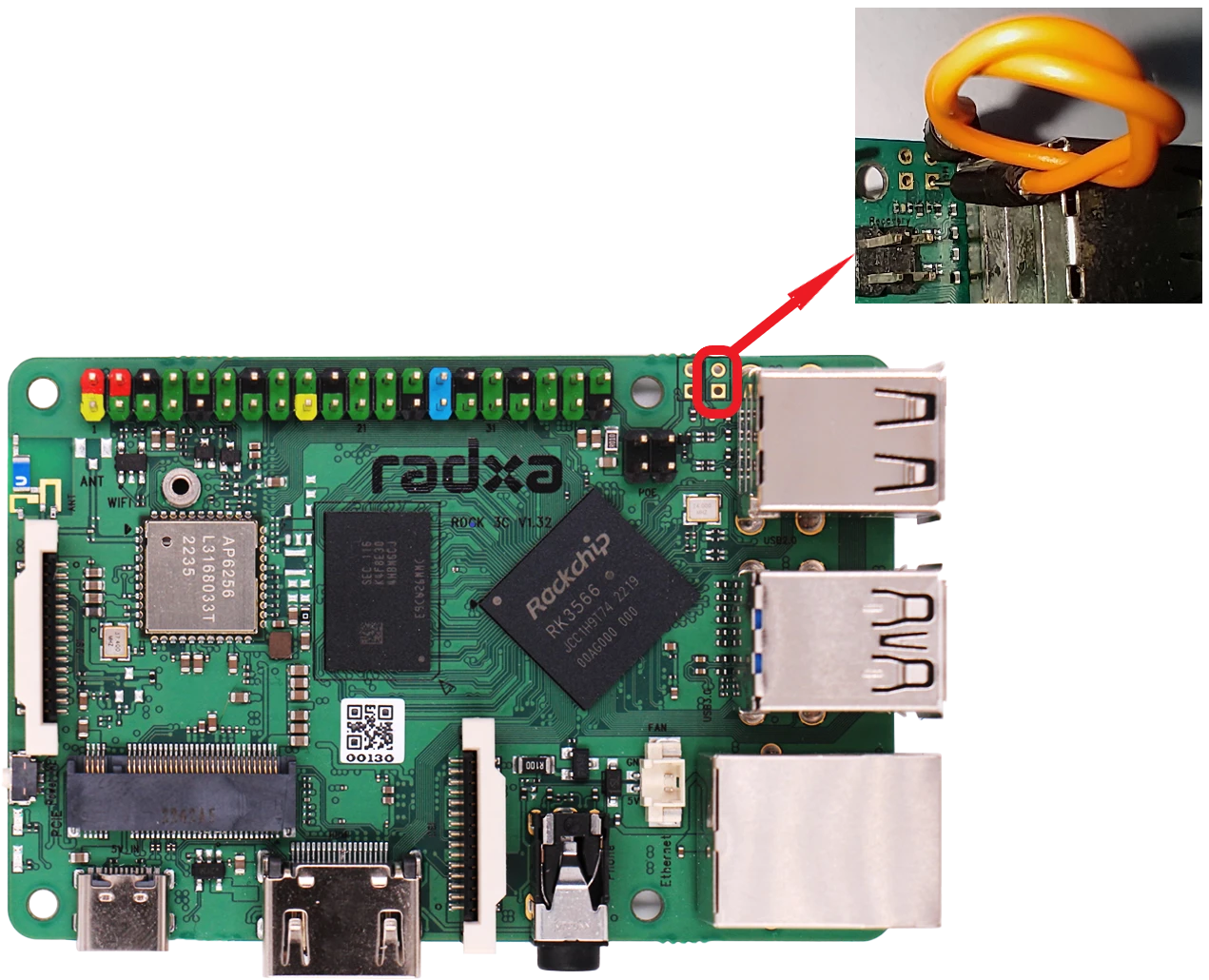
-
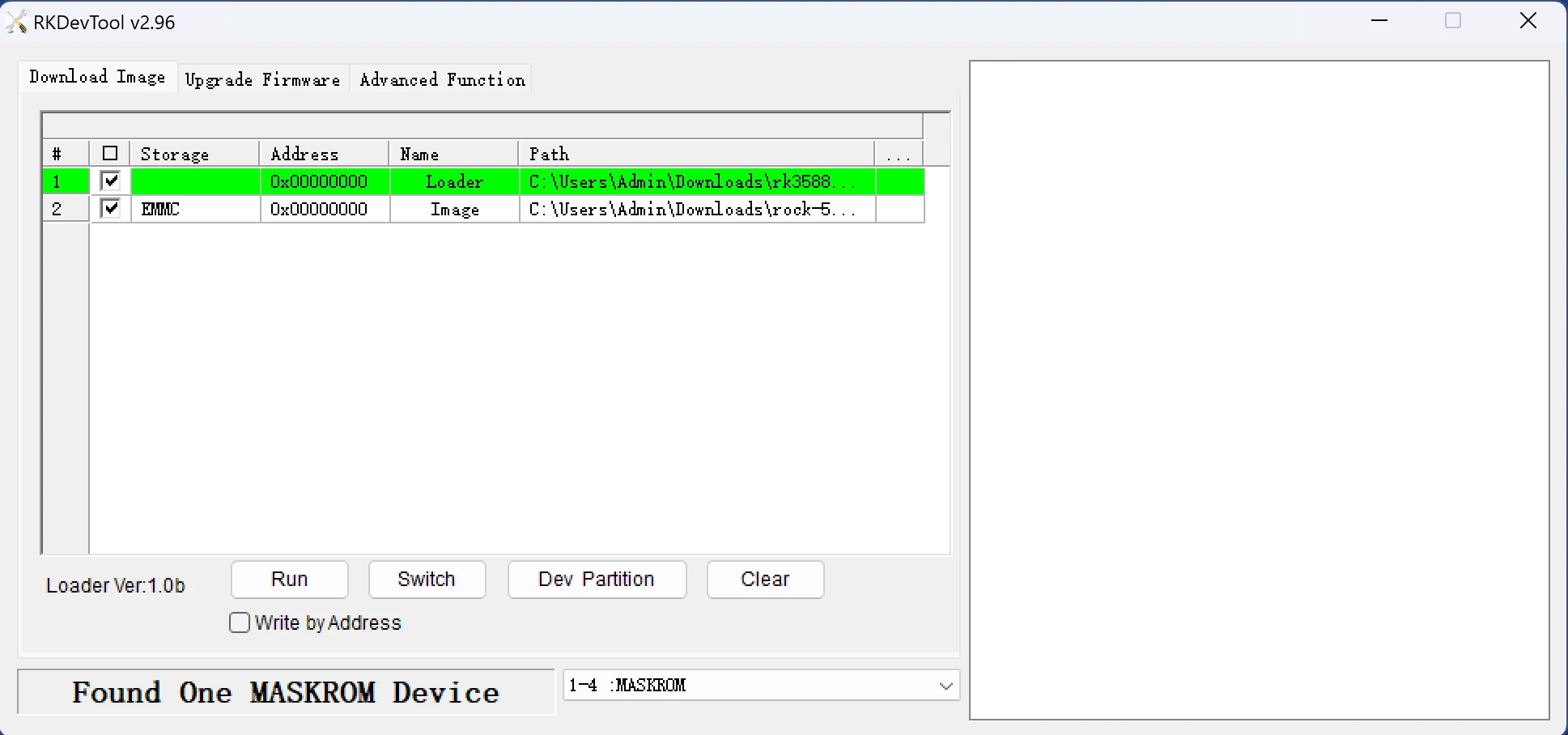
Power on the device and check if it has successfully entered Maskrom mode by using the corresponding tool, the following is an example of the correct entry.
- RKDevTool
- rkdeveloptool
- upgrade_tool
    sudo rkdeveloptool ld # List connected devices
    DevNo=1 Vid=0x2207,Pid=0x350b,LocationID=106 Maskrom
$ sudo . /upgrade_tool # List connected devices
Using /home/rock/Linux_Upgrade_Tool/config.ini
Program Log will save in the /root/upgrade_tool/log/
List of rockusb connected
DevNo=1 Vid=0x2207,Pid=0x350b,LocationID=21 Mode=Maskrom
Found 1 rockusb,Select input DevNo,Rescan press <R>,Quit press <Q>:
Special Circumstances
Due to the logical limitation of the SoC design, after flashing the SPI image in the SPI Flash, it may be possible to enter the Maskrom mode directly when booting from eMMC or microSD card. In this case, you need to disconnect the SPI to enter the system, and erase the SPI to recover.
Erase the SPI Flash via RKDevTool:
- Remove system storage media
- Power on and enter Maskrom mode
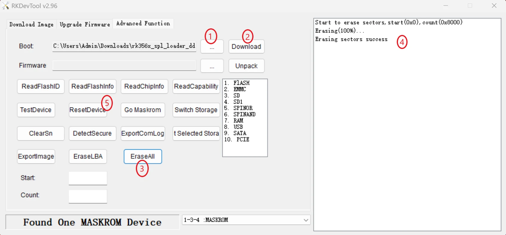
- Download the loader file: Annotation 1 to select the loader file, Annotation 2 to download the loader file
- Erase All: Annotation 3 Erase All, Annotation 4 Erase Complete
- Reboot the device: Annotation 5 Reboot the device
In particular, if you still cannot access the system by shorting the reserved SPI shorting hole and you need to access the system, you can power on the system by grounding the clk pin of the SPI Flash directly, as follows.
- Install the eMMC or microSD card with the system programmed on it
- Use the female connector of a male-to-female DuPont cable to connect to the ground pin of the 40-pin connector, which is marked in black on the connector
- Use the male end of the male-to-female DuPont cable to connect to the clk pin of the SPI Flash, which is shown in the following figure on the ROCK 3C
- Power on
- Disconnect after the serial port log indicates booting to U-Boot
Power up and power on 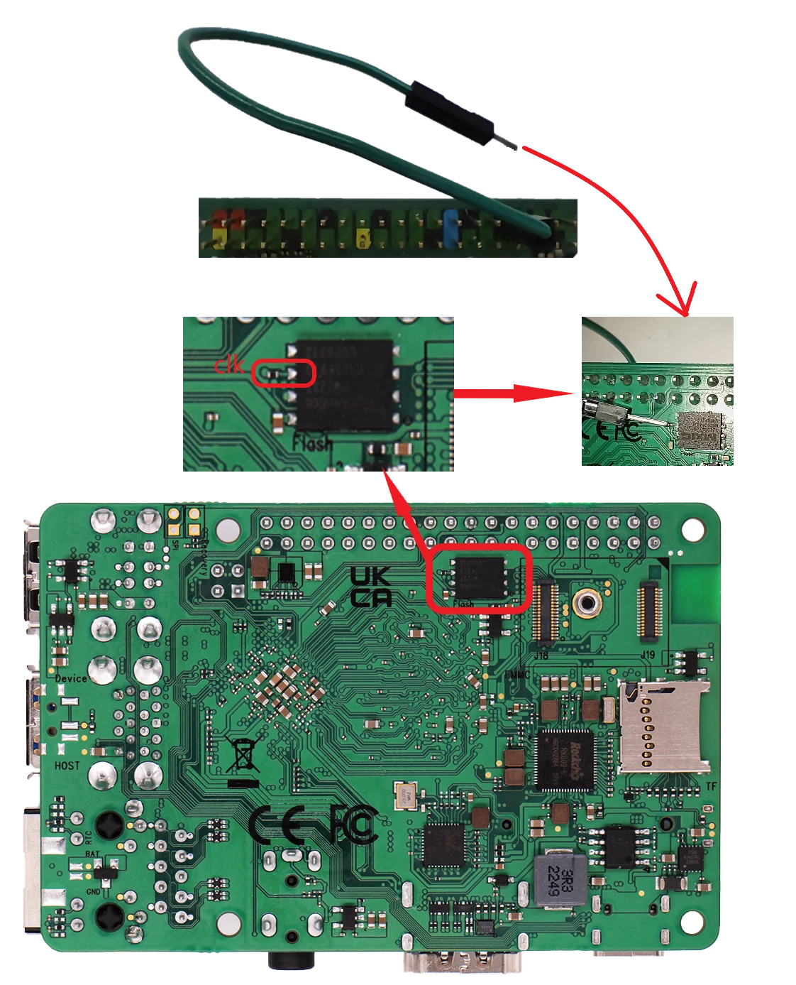
After entering the system, you can execute the following command to view the SPI Flash block number:
    ls /dev/mtdblock*
    # Typically, the block number of SPI Flash is as follows, which can be confirmed by the partition size
    /dev/mtd0
Afterwards, the SPI Flash can be cleared with the following command:
sudo erase_flashall /dev/mtd0