Hardware Interface Description
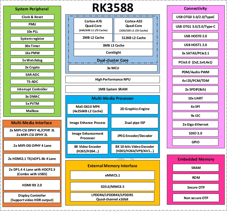
Chip block diagram
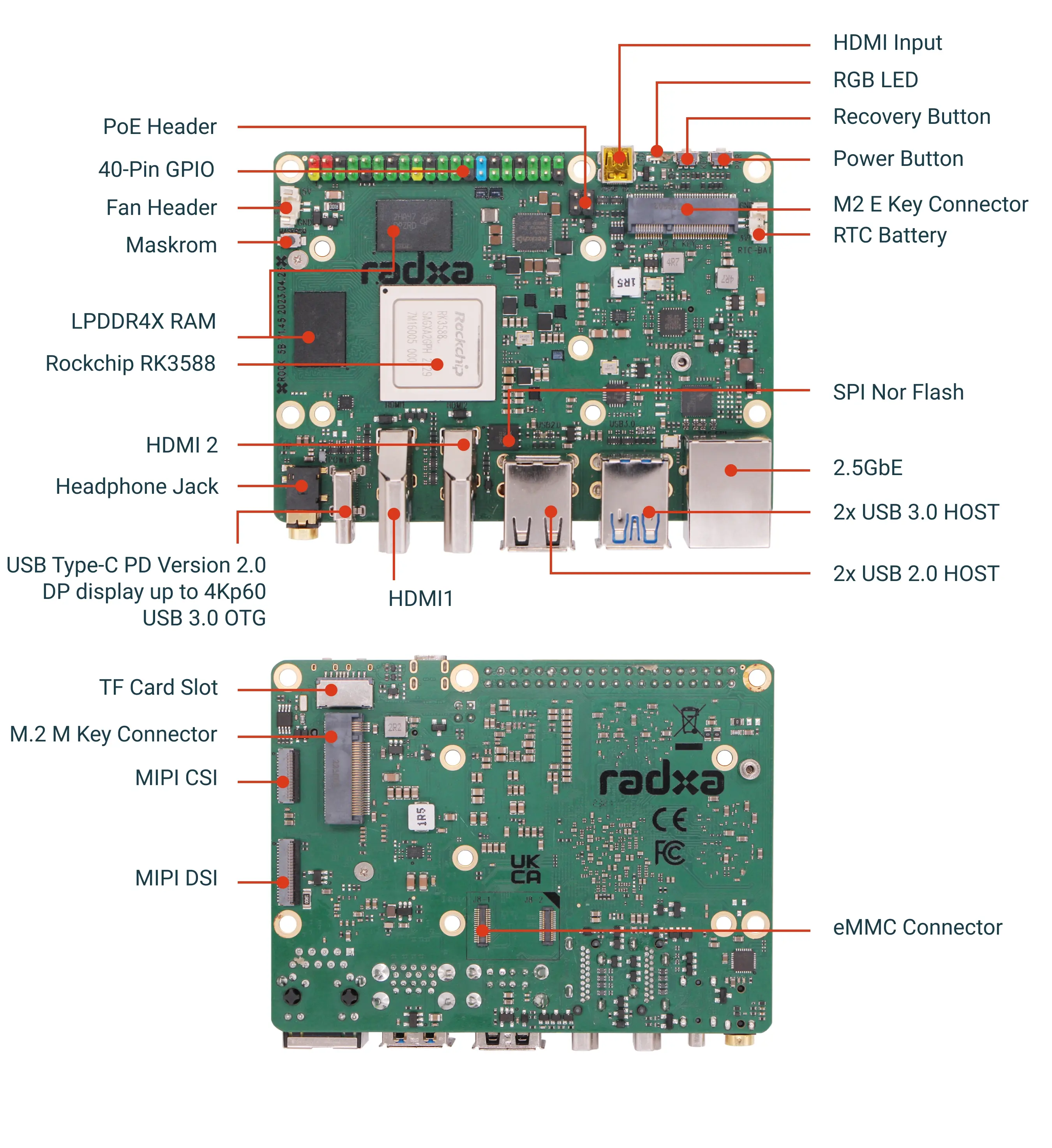
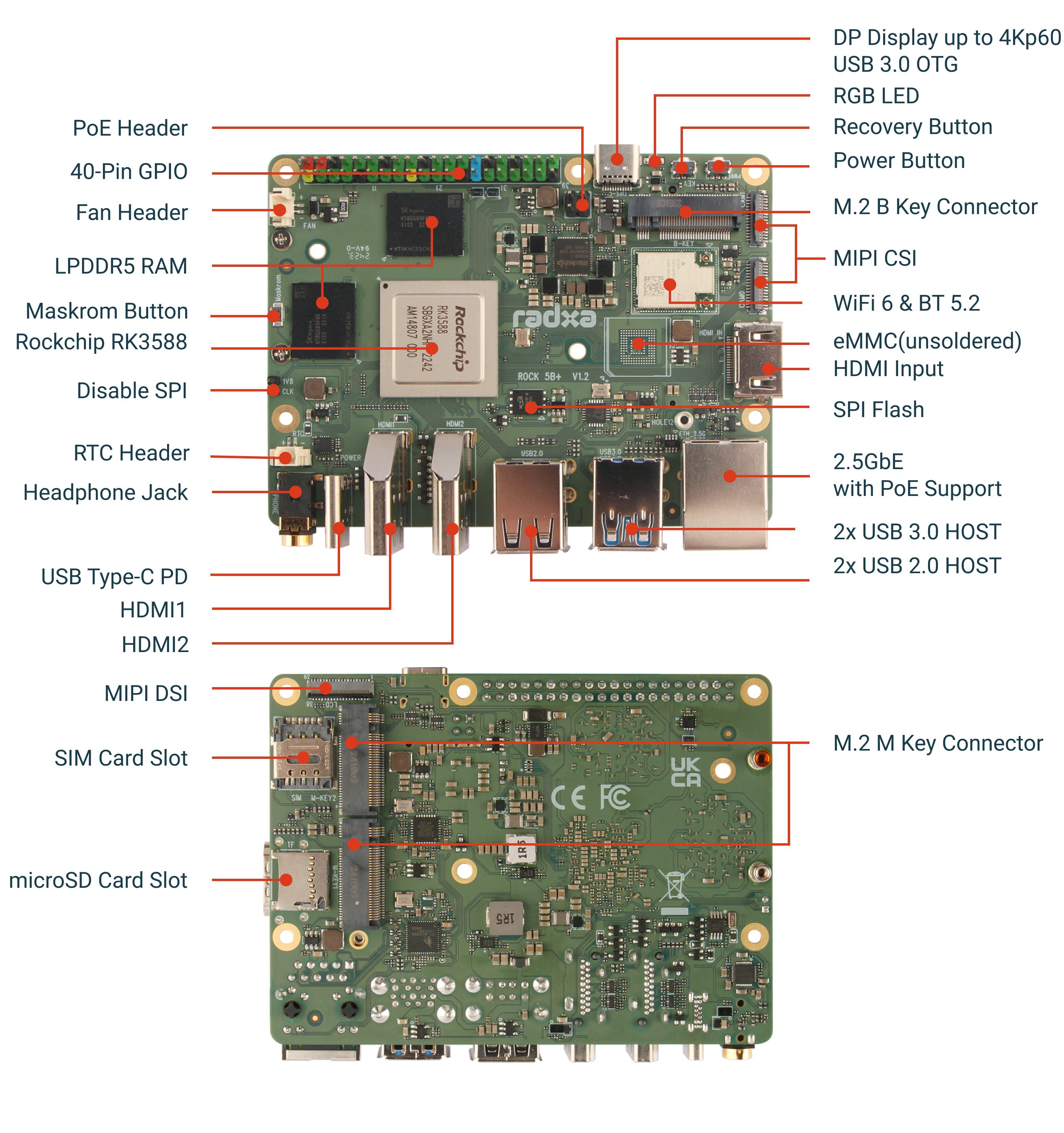
Physical photographs
- ROCK 5B
- ROCK 5B+
Interface details
eMMC
- ROCK 5B
- ROCK 5B+
| Name | Pin# | Pin# | Name |
|---|---|---|---|
| GND | 1 | 34 | GND |
| EMMC_D5 | 2 | 33 | eMMC_D6 |
| GND | 3 | 32 | GND |
| EMMC_D4 | 4 | 31 | eMMC_D7 |
| GND | 5 | 30 | GND |
| EMMC_D0 | 6 | 29 | eMMC_D1 |
| GND | 7 | 28 | GND |
| EMMC_CLK | 8 | 27 | eMMC_D2 |
| GND | 9 | 26 | GND |
| EMMC_D3 | 10 | 25 | eMMC_CMD |
| GND | 11 | 24 | GND |
| EMMC_RSTN | 12 | 23 | VCC_3V3_S3 |
| GND | 13 | 22 | VCC_3V3_S3 |
| GND | 14 | 21 | VCC_1V8_S3 |
| eMMC_DATA_STROBE | 15 | 20 | VCC_1V8_S3 |
| GND | 16 | 19 | GND |
| GND | 17 | 18 | GND |
| GND | |||
| GND | 35 | GND | |
| GND | 36 | GND | |
| GND | 37 | GND | |
| GND | 38 | GND | |
| GND | 39 | GND | |
| GND | 40 | GND | |
| GND | 41 | GND | |
| GND | 42 | GND | |
| GND | 43 | GND | |
| GND | 44 | GND | |
| GND | 45 | GND | |
| GND | 46 | GND | |
| GND | 47 | GND | |
| GND | 48 | GND | |
| GND | 49 | GND |
| Name | Pin# | Pin# | Name |
|---|---|---|---|
| eMMC_D0 | A3 | C6 | VCC_1V8_S3 |
| eMMC_D1 | A4 | M4 | VCC_1V8_S3 |
| eMMC_D2 | A5 | N4 | VCC_1V8_S3 |
| eMMC_D3 | B2 | P3 | VCC_1V8_S3 |
| eMMC_D4 | B3 | P5 | VCC_1V8_S3 |
| eMMC_D5 | B4 | E6 | VCC_3V3_S3 |
| eMMC_D6 | B5 | F5 | VCC_3V3_S3 |
| eMMC_D7 | B6 | J10 | VCC_3V3_S3 |
| eMMC_CMD | M5 | K9 | VCC_3V3_S3 |
| eMMC_CLKOUT | M6 | J5 | GND |
| eMMC_RSTn | K5 | A6 | GND |
| GND | C2 | C4 | GND |
| eMMC_DATA_STROBE | H5 | E7 | GND |
| NC | E9 | G5 | GND |
| NC | E10 | H10 | GND |
| NC | F10 | K8 | GND |
| NC | K10 | N2 | GND |
| N5 | GND | ||
| P4 | GND | ||
| P6 | GND |
GPIO
- GPIO Voltage
| GPIO | Voltage | MAX |
|---|---|---|
| All GPIO | 3.3V | 3.63V |
| SARADC_IN4 | 3.3V | 1.8V |
- GPIO Pinout
- ROCK 5B
- ROCK 5B+
| GPIO number | Function8 | Function7 | Function6 | Function5 | Function4 | Function3 | Function2 | Function1 | Pin# | Pin# | Function1 | Function2 | Function3 | Function4 | Function5 | Function6 | Function7 | Function8 | GPIO number |
|---|---|---|---|---|---|---|---|---|---|---|---|---|---|---|---|---|---|---|---|
| +3.3V | 1 | 2 | +5.0V | ||||||||||||||||
| 139 | I2S1_SDO2_M0 | I2C7_SDA_M3 | UART8_CTSN_M0 | PWM15_IR_M1 | GPIO4_B3 | 3 | 4 | +5.0V | |||||||||||
| 138 | I2S1_SDO1_M0 | I2C7_SCL_M3 | UART8_RTSN_M0 | PWM14_M1 | GPIO4_B2 | 5 | 6 | GND | |||||||||||
| 115 | SPI1_CS1_M1 | I2C8_SDA_M4 | UART7_CTSN_M1 | PWM15_IR_M0 | GPIO3_C3 | 7 | 8 | GPIO0_B5 | UART2_TX_M0 | I2C1_SCL_M0 | I2S1_MCLK_M1 | 13 | |||||||
| GND | 9 | 10 | GPIO0_B6 | UART2_RX_M0 | I2C1_SDA_M0 | I2S1_SCLK_M1 | 14 | ||||||||||||
| 113 | SPI1_CLK_M1 | UART7_RX_M1 | GPIO3_C1 | 11 | 12 | GPIO3_B5 | PWM12_M0 | UART3_TX_M1 | I2S2_SCLK_M1 | 109 | |||||||||
| 111 | SPI1_MOSI_M1 | I2C3_SCL_M1 | GPIO3_B7 | 13 | 14 | GND | |||||||||||||
| 112 | SPI1_MISO_M1 | I2C3_SDA_M1 | UART7_TX_M1 | GPIO3_C0 | 15 | 16 | GPIO3_A4 | 100 | |||||||||||
| +3.3V | 17 | 18 | GPIO4_C4 | PWM5_M2 | SPI3_MISO_M0 | 148 | |||||||||||||
| 42 | SPI0_MOSI_M2 | UART4_RX_M2 | GPIO1_B2 | 19 | 20 | GND | |||||||||||||
| 41 | SPI0_MISO_M2 | GPIO1_B1 | 21 | 22 | SARADC_IN4 | ||||||||||||||
| 43 | SPI0_CLK_M2 | UART4_TX_M2 | GPIO1_B3 | 23 | 24 | GPIO1_B4 | UART7_RX_M2 | SPI0_CS0_M2 | 44 | ||||||||||
| GND | 25 | 26 | GPIO1_B5 | UART7_TX_M2 | SPI0_CS1_M2 | 45 | |||||||||||||
| 150 | SPI3_CLK_M0 | I2C0_SDA_M1 | PWM7_IR_M3 | GPIO4_C6 | 27 | 28 | GPIO4_C5 | PWM6_M2 | I2C0_SCL_M1 | SPI3_MOSI_M0 | 149 | ||||||||
| 63 | UART1_CTSN_M1 | PWM15_IR_M3 | GPIO1_D7 | 29 | 30 | GND | |||||||||||||
| 47 | SPDIF_TX_M0 | UART1_RX_M1 | PWM13_M2 | GPIO1_B7 | 31 | 32 | GPIO3_C2 | PWM14_M0 | UART7_RTSN_M1 | I2C8_SCL_M4 | SPI1_CS0_M1 | 114 | |||||||
| 103 | PWM8_M0 | GPIO3_A7 | 33 | 34 | GND | ||||||||||||||
| 110 | I2S2_LRCK_M1 | UART3_RX_M1 | PWM13_M0 | GPIO3_B6 | 35 | 36 | GPIO3_B1 | PWM2_M1 | UART2_TX_M2 | 105 | |||||||||
| GPIO0_A0 | 37 | 38 | GPIO3_B2 | PWM3_IR_M1 | UART2_RX_M2 | I2S2_SDI_M1 | 106 | ||||||||||||
| GND | 39 | 40 | GPIO3_B3 | UART2_RTSN | I2S2_SDO_M1 | 107 |
| GPIO number | Function8 | Function7 | Function6 | Function5 | Function4 | Function3 | Function2 | Function1 | Pin# | Pin# | Function1 | Function2 | Function3 | Function4 | Function5 | Function6 | Function7 | Function8 | GPIO number |
|---|---|---|---|---|---|---|---|---|---|---|---|---|---|---|---|---|---|---|---|
| +3.3V | 1 | 2 | +5.0V | ||||||||||||||||
| 139 | I2S1_SDO2_M0 | I2C7_SDA_M3 | UART8_CTSN_M0 | PWM15_IR_M1 | GPIO4_B3 | 3 | 4 | +5.0V | |||||||||||
| 138 | I2S1_SDO1_M0 | I2C7_SCL_M3 | UART8_RTSN_M0 | PWM14_M1 | GPIO4_B2 | 5 | 6 | GND | |||||||||||
| 115 | SPI1_CS1_M1 | I2C8_SDA_M4 | UART7_CTSN_M1 | PWM15_IR_M0 | GPIO3_C3 | 7 | 8 | GPIO0_B5 | UART2_TX_M0 | I2C1_SCL_M0 | I2S1_MCLK_M1 | 13 | |||||||
| GND | 9 | 10 | GPIO0_B6 | UART2_RX_M0 | I2C1_SDA_M0 | I2S1_SCLK_M1 | 14 | ||||||||||||
| 113 | SPI1_CLK_M1 | UART7_RX_M1 | GPIO3_C1 | 11 | 12 | GPIO3_B5 | PWM12_M0 | UART3_TX_M1 | I2S2_SCLK_M1 | 109 | |||||||||
| 111 | SPI1_MOSI_M1 | I2C3_SCL_M1 | GPIO3_B7 | 13 | 14 | GND | |||||||||||||
| 112 | SPI1_MISO_M1 | I2C3_SDA_M1 | UART7_TX_M1 | GPIO3_C0 | 15 | 16 | GPIO3_A4 | 100 | |||||||||||
| +3.3V | 17 | 18 | GPIO4_C4 | PWM5_M2 | SPI3_MISO_M0 | 148 | |||||||||||||
| 42 | SPI0_MOSI_M2 | UART4_RX_M2 | GPIO1_B2 | 19 | 20 | GND | |||||||||||||
| 41 | SPI0_MISO_M2 | GPIO1_B1 | 21 | 22 | SARADC_IN4 | ||||||||||||||
| 43 | SPI0_CLK_M2 | UART4_TX_M2 | GPIO1_B3 | 23 | 24 | GPIO1_B4 | UART7_RX_M2 | SPI0_CS0_M2 | 44 | ||||||||||
| GND | 25 | 26 | GPIO1_B5 | UART7_TX_M2 | SPI0_CS1_M2 | 45 | |||||||||||||
| 150 | SPI3_CLK_M0 | I2C0_SDA_M1 | PWM7_IR_M3 | GPIO4_C6 | 27 | 28 | GPIO4_C5 | PWM6_M2 | I2C0_SCL_M1 | SPI3_MOSI_M0 | 149 | ||||||||
| 35 | I2C4_SCL_M3 | PWM1_M2 | GPIO1_A3 | 29 | 30 | GND | |||||||||||||
| 34 | I2C4_SDA_M3 | PWM0_M2 | GPIO1_A2 | 31 | 32 | GPIO3_C2 | PWM14_M0 | UART7_RTSN_M1 | I2C8_SCL_M4 | SPI1_CS0_M1 | 114 | ||||||||
| 103 | PWM8_M0 | GPIO3_A7 | 33 | 34 | GND | ||||||||||||||
| 110 | I2S2_LRCK_M1 | UART3_RX_M1 | PWM13_M0 | GPIO3_B6 | 35 | 36 | GPIO3_B1 | PWM2_M1 | UART2_TX_M2 | 105 | |||||||||
| GPIO0_A0 | 37 | 38 | GPIO3_B2 | PWM3_IR_M1 | UART2_RX_M2 | I2S2_SDI_M1 | 106 | ||||||||||||
| GND | 39 | 40 | GPIO3_B3 | UART2_RTSN | I2S2_SDO_M1 | 107 |
Gigabit Ethernet
- ROCK 5B/5B+
| Pin# | Name | Pin# | Name |
|---|---|---|---|
| 1 | MDI0+ | 2 | MDI0- |
| 3 | MDI1+ | 4 | GND |
| 5 | GND | 6 | MDI1- |
| 7 | MDI2+ | 8 | MDI2- |
| 9 | MDI3+ | 10 | MDI3- |
| 11 | GND | 12 | GND |
| 13 | GND | 14 | GND |
| 15 | LED0 | 16 | LED1 |
| 17 | V3P3A | 18 | LED2 |
| 19 | GND | 20 | GND |
Maskrom Button
| Name | Pin# | Pin# | Name |
|---|---|---|---|
| GND | 1 | 2 | BOOT_SARADC_IN0 |
MIPI CSI
- ROCK 5B
- ROCK 5B+
| Pin# | Name | Pin# | Name |
|---|---|---|---|
| 1 | GND | 17 | MIPI_CSI0_RX_CLK0N |
| 2 | MIPI_CSI0_RX_D3N | 18 | MIPI_CSI0_RX_CLK0P |
| 3 | MIPI_CSI0_RX_D3P | 19 | GND |
| 4 | GND | 20 | MIPI_CAM3_CLKOUT |
| 5 | MIPI_CSI0_RX_D2N | 21 | GND |
| 6 | MIPI_CSI0_RX_D2P | 22 | MIPI_CAM1_CLKOUT |
| 7 | GND | 23 | MIPI_CSI0_PDN0_H |
| 8 | MIPI_CSI0_RX_CLK1N | 24 | I2C3_SCL_M0_MIPI |
| 9 | MIPI_CSI0_RX_CLK1P | 25 | I2C3_SDA_M0_MIPI |
| 10 | GND | 26 | MIPI_CSI0_PDN1_H |
| 11 | MIPI_CSI0_RX_D1N | 27 | CM_RST_L |
| 12 | MIPI_CSI0_RX_D1P | 28 | VCC_3V3_S3 |
| 13 | GND | 29 | VCC_3V3_S3 |
| 14 | MIPI_CSI0_RX_D0N | 30 | VCC5V0_SYS |
| 15 | MIPI_CSI0_RX_D0P | 31 | VCC5V0_SYS |
| 16 | GND |
CAM0
| Pin# | Name | Pin# | Name |
|---|---|---|---|
| 1 | GND | 17 | MIPI_CSI0_RX_CLK0N |
| 2 | MIPI_CSI0_RX_D3N | 18 | MIPI_CSI0_RX_CLK0P |
| 3 | MIPI_CSI0_RX_D3P | 19 | GND |
| 4 | GND | 20 | MIPI_CAM3_CLKOUT |
| 5 | MIPI_CSI0_RX_D2N | 21 | GND |
| 6 | MIPI_CSI0_RX_D2P | 22 | MIPI_CAM1_CLKOUT |
| 7 | GND | 23 | MIPI_CSI0_PDN0_H |
| 8 | MIPI_CSI0_RX_CLK1N | 24 | I2C3_SCL_M0_MIPI |
| 9 | MIPI_CSI0_RX_CLK1P | 25 | I2C3_SDA_M0_MIPI |
| 10 | GND | 26 | MIPI_CSI0_PDN1_H |
| 11 | MIPI_CSI0_RX_D1N | 27 | CM_RST_L_1 |
| 12 | MIPI_CSI0_RX_D1P | 28 | VCC_3V3_S3 |
| 13 | GND | 29 | VCC_3V3_S3 |
| 14 | MIPI_CSI0_RX_D0N | 30 | VCC_5V |
| 15 | MIPI_CSI0_RX_D0P | 31 | VCC_5V |
| 16 | GND |
CAM1
| Pin# | Name | Pin# | Name |
|---|---|---|---|
| 1 | GND | 17 | MIPI_CSI1_RX_CLK0N |
| 2 | MIPI_CSI1_RX_D3N | 18 | MIPI_CSI1_RX_CLK0P |
| 3 | MIPI_CSI1_RX_D3P | 19 | GND |
| 4 | GND | 20 | MIPI_CAM4_CLKOUT |
| 5 | MIPI_CSI1_RX_D2N | 21 | GND |
| 6 | MIPI_CSI1_RX_D2P | 22 | MIPI_CAM2_CLKOUT |
| 7 | GND | 23 | MIPI_CSI1_PDN2_H |
| 8 | MIPI_CSI1_RX_CLK1N | 24 | I2C4_SCL |
| 9 | MIPI_CSI1_RX_CLK1P | 25 | I2C4_SDA |
| 10 | GND | 26 | MIPI_CSI1_PDN4_H |
| 11 | MIPI_CSI1_RX_D1N | 27 | CAM2_RST_L |
| 12 | MIPI_CSI1_RX_D1P | 28 | VCC_3V3_S3 |
| 13 | GND | 29 | VCC_3V3_S3 |
| 14 | MIPI_CSI1_RX_D0N | 30 | VCC_5V |
| 15 | MIPI_CSI1_RX_D0P | 31 | VCC_5V |
| 16 | GND |
MIPI DSI
- ROCK 5B
- ROCK 5B+
| Pin# | Name | Pin# | Name |
|---|---|---|---|
| 1 | LCD_3V3 | 21 | GND |
| 2 | VCC_1V8_S0 | 22 | GND |
| 3 | GPIO0-A0 | 23 | TP_RST_L |
| 4 | LCD_RESET | 24 | LCD_3V3 |
| 5 | NC | 25 | TP_INT_L |
| 6 | GND | 26 | I2C6_SDA_M0 |
| 7 | MIPI_DPHY1_TX_D0N | 27 | I2C6_SCL_M0 |
| 8 | MIPI_DPHY1_TX_D0P | 28 | GND |
| 9 | GND | 29 | GND |
| 10 | MIPI_DPHY1_TX_D1N | 30 | LCD_3V3 |
| 11 | MIPI_DPHY1_TX_D1P | 31 | LCD_3V3 |
| 12 | GND | 32 | GND |
| 13 | MIPI_DPHY1_TX_CLKN | 33 | GND |
| 14 | MIPI_DPHY1_TX_CLKP | 34 | VCC_LEDK |
| 15 | GND | 35 | VCC_LEDK |
| 16 | MIPI_DPHY1_TX_D2N | 36 | NC |
| 17 | MIPI_DPHY1_TX_D2P | 37 | NC |
| 18 | GND | 38 | VCC_LEDA |
| 19 | MIPI_DPHY1_TX_D3N | 39 | VCC_LEDA |
| 20 | MIPI_DPHY1_TX_D3P | 40 | GND |
| 41 | GND |
| Pin# | Name | Pin# | Name |
|---|---|---|---|
| 1 | LCD_3V3 | 21 | GND |
| 2 | VCC_1V8_S0 | 22 | GND |
| 3 | GPIO0-A0 | 23 | TP_RST_LCD |
| 4 | LCD_RESET | 24 | LCD_3V3 |
| 5 | GPIO1_A3_1 | 25 | TP_INT_LCD |
| 6 | GND | 26 | TP_SDA_LCD |
| 7 | MIPI_DPHY1_TX_D0N | 27 | TP_SCL_LCD |
| 8 | MIPI_DPHY1_TX_D0P | 28 | GND |
| 9 | GND | 29 | GND |
| 10 | MIPI_DPHY1_TX_D1N | 30 | LCD_3V3 |
| 11 | MIPI_DPHY1_TX_D1P | 31 | LCD_3V3 |
| 12 | GND | 32 | GND |
| 13 | MIPI_DPHY1_TX_CLKN | 33 | GND |
| 14 | MIPI_DPHY1_TX_CLKP | 34 | VCC_LEDK |
| 15 | GND | 35 | VCC_LEDK |
| 16 | MIPI_DPHY1_TX_D2N | 36 | GND |
| 17 | MIPI_DPHY1_TX_D2P | 37 | GND |
| 18 | GND | 38 | VCC_LEDA |
| 19 | MIPI_DPHY1_TX_D3N | 39 | VCC_LEDA |
| 20 | MIPI_DPHY1_TX_D3P | 40 | GND |
| 41 | GND |
PCIe
- PCIe B Key
- ROCK 5B
- ROCK 5B+
ROCK 5B has no PCIe B Key
| Pin# | Name | Pin# | Name |
|---|---|---|---|
| 1 | NC | 2 | 3V3_4G |
| 3 | GND | 4 | 3V3_4G |
| 5 | GND | 6 | 4G_PWREN |
| 7 | USB4_DP | 8 | 4G_DISABLE |
| 9 | USB4_DM | 10 | NC |
| 11 | GND | ||
| 20 | I2S2_LRCK_M0_BT | ||
| 21 | GND | 22 | I2S2_SDI_M0_BT |
| 23 | 4G_WAKE_ON_HOST | 24 | I2S2_SDO_M0_BT |
| 25 | NC | 26 | W_DISABLE2 |
| 27 | GND | 28 | NC |
| 29 | NC | 30 | SIM1_RESET |
| 31 | NC | 32 | SIM1_CLK |
| 33 | GND | 34 | SIM1_DATA |
| 35 | NC | 36 | SIM1_PWR |
| 37 | NC | 38 | DEVSLP |
| 39 | GND | 40 | NC |
| 41 | NC | 42 | NC |
| 43 | NC | 44 | NC |
| 45 | GND | 46 | NC |
| 47 | NC | 48 | NC |
| 49 | NC | 50 | NC |
| 51 | GND | 52 | NC |
| 53 | NC | 54 | NC |
| 55 | NC | 56 | NC |
| 57 | GND | 58 | NC |
| 59 | NC | 60 | I2S2_SCLK_M0_BT |
| 61 | NC | 62 | NC |
| 63 | NC | 64 | NC |
| 65 | NC | 66 | SIM1_DET |
| 67 | 4G_RESET | 68 | NC |
| 69 | GND | 70 | 3V3_4G |
| 71 | GND | 72 | 3V3_4G |
| 73 | GND | 74 | 3V3_4G |
| 75 | GND | 76 | GND |
| 77 | GND | 78 | GND |
| 79 | NC | 80 | NC |
- PCIe E Key
- ROCK 5B
- ROCK 5B+
| Pin# | Name | Pin# | Name | Pin# | Name | Pin# | Name |
|---|---|---|---|---|---|---|---|
| 1 | GND | 21 | WIFI_WAKE_HOST_H_GPIO3_D5 | 49 | PCIE20_REFCLKN | 69 | GND |
| 2 | VCC3V3_WF | 22 | UART1_RX_M0 | 50 | WIFIBT_32KIN_1T1R | 70 | BT_WAKE |
| 3 | USB2_M2_DP | 23 | WIFI_REG_ON | 51 | GND | 71 | NC |
| 4 | VCC3V3_WF | 32 | UART1_TX_M0 | 52 | PCIE_PERSTN | 72 | VCC3V3_WF |
| 5 | USB2_M2_DM | 33 | GND | 53 | PCIE_CLKREQN | 73 | NC |
| 6 | WIFI_LED | 34 | UART1_CTS_M | 54 | HOST_WAKE_BT_H | 74 | VCC3V3_WF |
| 7 | GND | 35 | PCIE_TXP | 55 | PCIE_WAKEN | 75 | GND |
| 8 | PCM_CLK/I2S_SCK | 36 | UART1_RTS_M | 56 | BT_REG_ON_H | 76 | GND |
| 9 | SDIO_CLK | 37 | PCIE_TXN | 57 | GND | 77 | GND |
| 10 | PCM_SYNC/I2S_WS | 38 | NC | 58 | I2C4_SDA_M1 | 78 | NC |
| 11 | SDMMC2_CMD_M0 | 39 | GND | 59 | NC | 79 | NC |
| 12 | PCM_OUT/I2S SD_OUT | 40 | NC | 60 | I2C4_SCL_M1 | ||
| 13 | SDMMC2_D0_M0 | 41 | PCIE20_RXP | 61 | NC | ||
| 14 | PCM_IN/I2S SD_IN | 42 | BT_REG_NO | 62 | NC | ||
| 15 | SDMMC2_D1_M0 | 43 | PCIE20_RXN | 63 | GND | ||
| 16 | NC | 44 | NC | 64 | NC | ||
| 17 | SDMMC2_D2_M0 | 45 | GND | 65 | NC | ||
| 18 | GND | 46 | NC | 66 | NC | ||
| 19 | SDMMC2_D3_M0 | 47 | PCIE20_REFC | 67 | NC | ||
| 20 | BT_WAKE_HOST_H_GPIO4_B4 | 48 | NC | 68 | NC |
ROCK 5B+ has no PCIe E Key
- PCIe M Key
- ROCK 5B
- ROCK 5B+
| Pin# | Name | Pin# | Name |
|---|---|---|---|
| 1 | GND | 2 | VCC3V3_PCIE30 |
| 3 | GND | 4 | VCC3V3_PCIE30 |
| 5 | PCIE30_PORT1_RX3N | 6 | NC |
| 7 | PCIE30_PORT1_RX3P | 8 | NC |
| 9 | GND | 10 | NC |
| 11 | PCIE30_PORT1_TX3N | 12 | VCC3V3_PCIE30 |
| 13 | PCIE30_PORT1_TX3P | 14 | VCC3V3_PCIE30 |
| 15 | GND | 16 | VCC3V3_PCIE30 |
| 17 | PCIE30_PORT1_RX2N | 18 | VCC3V3_PCIE30 |
| 19 | PCIE30_PORT1_RX2P | 20 | NC |
| 21 | GND | 22 | NC |
| 23 | PCIE30_PORT1_TX2N | 24 | NC |
| 25 | PCIE30_PORT1_TX2P | 26 | NC |
| 27 | GND | 28 | NC |
| 29 | PCIE30_PORT0_RX1N | 30 | NC |
| 31 | PCIE30_PORT0_RX1P | 32 | NC |
| 33 | GND | 34 | NC |
| 35 | PCIE30_PORT0_TX1N | 36 | NC |
| 37 | PCIE30_PORT0_TX1P | 38 | NC |
| 39 | GND | 40 | NC |
| 41 | PCIE30_PORT0_RX0N | 42 | NC |
| 43 | PCIE30_PORT0_RX0P | 44 | CLK_3P |
| 45 | GND | 46 | CLK_3N |
| 47 | PCIE30_PORT0_TX0N | 48 | NC |
| 49 | PCIE30_PORT0_TX0P | 50 | PCIE30X4_PERSTn_M1_L |
| 51 | GND | 52 | PCIE30X4_CLKREQn_M1_L |
| 53 | PCIE30_REFCLKN_SLOT | 54 | PCIE30X4_WAKEn_M1_L |
| 55 | PCIE30_REFCLKP_SLOT | 56 | NC |
| 57 | GND | 58 | NC |
| 67 | NC | 68 | NC |
| 69 | NC | 70 | VCC3V3_PCIE30 |
| 71 | GND | 72 | VCC3V3_PCIE30 |
| 73 | GND | 74 | VCC3V3_PCIE30 |
| 75 | GND | 76 | GND |
| 77 | GND |
- PCIe M Key: PCIe3.0 x 2 Lane_1
| Pin# | Name | Pin# | Name |
|---|---|---|---|
| 1 | GND | 2 | VCC3V3_PCIE30 |
| 3 | GND | 4 | VCC3V3_PCIE30 |
| 5 | NC | 6 | NC |
| 7 | NC | 8 | NC |
| 9 | GND | 10 | NC |
| 11 | NC | 12 | VCC3V3_PCIE30 |
| 13 | NC | 14 | VCC3V3_PCIE30 |
| 15 | GND | 16 | VCC3V3_PCIE30 |
| 17 | NC | 18 | VCC3V3_PCIE30 |
| 19 | NC | 20 | NC |
| 21 | GND | 22 | NC |
| 23 | NC | 24 | NC |
| 25 | NC | 26 | NC |
| 27 | GND | 28 | NC |
| 29 | PCIE30_PORT0_RX1N | 30 | NC |
| 31 | PCIE30_PORT0_RX1P | 32 | NC |
| 33 | GND | 34 | NC |
| 35 | PCIE30_PORT0_TX1N | 36 | NC |
| 37 | PCIE30_PORT0_TX1P | 38 | NC |
| 39 | GND | 40 | NC |
| 41 | PCIE30_PORT0_RX0N | 42 | NC |
| 43 | PCIE30_PORT0_RX0P | 44 | NC |
| 45 | GND | 46 | NC |
| 47 | PCIE30_PORT0_TX0N | 48 | NC |
| 49 | PCIE30_PORT0_TX0P | 50 | PCIE30X4_PERSTn_M1_L |
| 51 | GND | 52 | PCIE30X4_CLKREQn_M1_L |
| 53 | PCIE30_REFCLKN_SLOT | 54 | PCIE30X4_WAKEn_M1_L |
| 55 | PCIE30_REFCLKP_SLOT | 56 | NC |
| 57 | GND | 58 | NC |
| 67 | NC | 68 | NC |
| 69 | NC | 70 | VCC3V3_PCIE30 |
| 71 | GND | 72 | VCC3V3_PCIE30 |
| 73 | GND | 74 | VCC3V3_PCIE30 |
| 75 | GND | 76 | GND |
| 77 | GND |
- PCIe M Key: PCIe3.0 x 2 Lane_2
| Pin# | Name | Pin# | Name |
|---|---|---|---|
| 1 | GND | 2 | 3V3_PCIE30_1 |
| 3 | GND | 4 | 3V3_PCIE30_1 |
| 5 | NC | 6 | NC |
| 7 | NC | 8 | NC |
| 9 | GND | 10 | NC |
| 11 | NC | 12 | 3V3_PCIE30_1 |
| 13 | NC | 14 | 3V3_PCIE30_1 |
| 15 | GND | 16 | 3V3_PCIE30_1 |
| 17 | NC | 18 | 3V3_PCIE30_1 |
| 19 | NC | 20 | NC |
| 21 | GND | 22 | NC |
| 23 | NC | 24 | NC |
| 25 | NC | 26 | NC |
| 27 | GND | 28 | NC |
| 29 | PCIE30_PORT1_RX3N | 30 | NC |
| 31 | PCIE30_PORT1_RX3P | 32 | NC |
| 33 | GND | 34 | NC |
| 35 | PCIE30_PORT1_TX3N | 36 | NC |
| 37 | PCIE30_PORT1_TX3P | 38 | NC |
| 39 | GND | 40 | NC |
| 41 | PCIE30_PORT1_RX2N | 42 | NC |
| 43 | PCIE30_PORT1_RX2P | 44 | NC |
| 45 | GND | 46 | NC |
| 47 | PCIE30_PORT1_TX2N | 48 | NC |
| 49 | PCIE30_PORT1_TX2P | 50 | PCIE30x2_PERSTn_M1 |
| 51 | GND | 52 | PCIE30x2_CLKREQn_M1 |
| 53 | PCIE30_REFCLKN_SLOT1 | 54 | PCIE30x2_WAKEn_M1 |
| 55 | PCIE30_REFCLKP_SLOT1 | 56 | NC |
| 57 | GND | 58 | NC |
| 67 | NC | 68 | NC |
| 69 | NC | 70 | 3V3_PCIE30_1 |
| 71 | GND | 72 | 3V3_PCIE30_1 |
| 73 | GND | 74 | 3V3_PCIE30_1 |
| 75 | GND | 76 | GND |
| 77 | GND |
POE
| Name | Pin# | Pin# | Name |
|---|---|---|---|
| TR2 | 4 | 2 | TR0 |
| TR3 | 3 | 1 | TR1 |
TF Card Slot
- ROCK 5B
- ROCK 5B+
| Pin# | Name |
|---|---|
| 1 | SDMMC0_D2 |
| 2 | SDMMC0_D3 |
| 3 | SDMMC0_CMD |
| 4 | VCC3V3_SYS |
| 5 | SDMMC0_CLK |
| 6 | GND |
| 7 | SDMMC0_D0 |
| 8 | SDMMC0_D1 |
| 9 | SDMMC0_DET_L |
| 10 | GND |
| 11 | GND |
| 12 | GND |
| 13 | GND |
| Pin# | Name |
|---|---|
| 1 | SDMMC_D2 |
| 2 | SDMMC_D3 |
| 3 | SDMMC_CMD |
| 4 | VCC_3V3_S3 |
| 5 | SDMMC_CLK |
| 6 | GND |
| 7 | SDMMC0_D0 |
| 8 | SDMMC0_D1 |
| 9 | SDMMC_DET_L |
| 10 | GND |
| A | GND |
| B | GND |
| C | GND |
| D | GND |
| E | GND |
| F | GND |
| G | GND |
| H | GND |