在 Linux 下控制 RP2040
Intel J4125 与 RP2040 和 40-PIN GPIO 的关系介绍
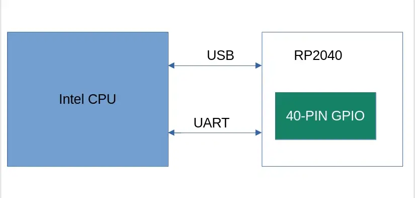
在 Radxa X2L 上集成了 Intel J4125 的 CPU 和一块 RP2040 MCU,两者通过 USB 和 UART 两种方式进行通信。 RP2040 在系统中以 USB 存储设备的形式存在,程序烧录时只需将文件拖拽至该 USB 设备中即可。 此外,它们还共用 UART 通信接口,使得 Intel J4125 能够通过 UART 控制 RP2040,例如,通过 UART 接口实现对 RP2040 GPIO 的操控。 两者关系,如图所示:
40-PIN 使用
为了操作 RP2040 上的 IO 资源, 我们需要一套完善的软件环境,如 MicroPython 或者 C/C++ SDK,在这里我们主要介绍一套 C/C++ SDK,即 pico-sdk 和 pico-example。 pico-sdk 主要是提供了一些操作 RP2040 的 API, 而 pico-examples 则为我们提供了一套程序编译框架,我们可以根据 pico-examples 提供的编译框架来添加我们自己的程序。
PICO-SDK
-
简介
Pico SDK(以下简称 SDK)提供了使用 C、C++ 或汇编语言为基于 RP2040 的设备(如 Raspberry Pi Pico/Radxa X2L)编写程序所需的标头、库和构建系统。
SDK 旨在提供非嵌入式 C 开发人员和嵌入式 C 开发人员都熟悉的 API 和编程环境。单个程序一次在设备上运行,并以常规方法启动main()。 支持标准 C/C++ 库以及用于访问 RP2040 的所有硬件(包括 PIO(可编程 IO))的 C 级库/API。
-
使用
既可以在 PC 端的 Linux 环境中下载 pico-sdk/pico-examples 以及安装相应工具,也可以在 Radxa X2L 的 Linux 环境下。为方便起见,我们可以直接在 Radxa X2L 的 Linux 环境中进行操作。
- 安装必要工具
sudo apt update -y
sudo apt install -y git cmake gcc-arm-none-eabi libnewlib-arm-none-eabi libstdc++-arm-none-eabi-newlib
- 获取代码
git clone https://github.com/raspberrypi/pico-sdk.git
cd pico-sdk
git submodule update --init
PICO-EXAMPLES
-
简介
pico-examples 是一个官方示例代码库,展示了如何使用 Raspberry Pi Pico 和 Pico SDK 来实现各种功能。 它提供了一系列的示例,涵盖了从基本 GPIO 操作到复杂的通信协议,使开发者能够快速上手并理解如何在 Pico 上进行开发。
-
使用
既可以在 PC 端的 Linux 环境中下载 pico-sdk/pico-examples 以及安装相应工具,也可以在 Radxa X2L 的 Linux 环境下。为方便起见,我们可以直接在 Radxa X2L 的 Linux 环境中进行操作。
- 获取代码
git clone https://github.com/raspberrypi/pico-examples.git --branch master
- 编译
export PICO_SDK_PATH=path/to/pico-sdk
cd pico-examples
mkdir build
cd build
cmake .. && make -j4
示例
RP2040 单独控制 40-PIN GPIO
- GPIO
- I2C
- PWM
- UART
GPIO
准备
- 一块 Radxa X2L
- 一个 LED
连接
| Radxa X2L | <--> | LED |
|---|---|---|
| PIN_5 | <--> | LED |
| PIN_1 | <--> | VCC |
| PIN_9 | <--> | GND |
这里的 PIN_5 对应 下面代码中的 GPIO29, 详细请参考 GPIO 定义
测试
-
将以下代码替换 pico-examples/blink/blink.c
blink.c
#include "pico/stdlib.h"
#define BLINK_PIN 29 // GPIO29

int main() {

    gpio_init(BLINK_PIN);
    gpio_set_dir(BLINK_PIN, GPIO_OUT);

    while (true) {
        gpio_put(BLINK_PIN, 1);
        sleep_ms(250);
        gpio_put(BLINK_PIN, 0);
        sleep_ms(250);
    }
} -
编译
cd pico-examples/build
rm -rf *
cmake ..
make -j$(nproc)
成功编译后,在 pico-examples/build/blink/ 目录下会产生一个名为 blink.uf2 的文件
-
烧录
- 重启 RP2040
-
将 blink.uf2 文件拖入到 RP2040 中,待 RP2040 消失后, LED 会开始闪烁
I2C
准备
- 一块 Radxa X2L
- 一个 I2C OLED 1306
连接
| Radxa X2L | <--> | OLED |
|---|---|---|
| PIN_5 | <--> | SCL |
| PIN_3 | <--> | SDA |
| PIN_1 | <--> | VCC |
| PIN_9 | <--> | GND |
这里的 PIN_5 对应 下面代码中的 GPIO29 的复用属性 I2C0 SDA, PIN_3 对应 下面代码中的 GPIO28 的复用属性 I2C0 SCL, 详细请参考 GPIO 定义
测试
- 将以下代码替换 pico-examples/i2c/lcd_1602_i2c/lcd_1602_i2c.c
lcd_1602_i2c.c
    #include <stdio.h>
    #include <string.h>
    #include "pico/stdlib.h"
    #include "hardware/i2c.h"
    #include "pico/binary_info.h"

    #define I2C_ID i2c0
    #define I2C_SDA_PIN 28
    #define I2C_SCL_PIN 29

    // commands
    const int LCD_CLEARDISPLAY = 0x01;
    const int LCD_RETURNHOME = 0x02;
    const int LCD_ENTRYMODESET = 0x04;
    const int LCD_DISPLAYCONTROL = 0x08;
    const int LCD_CURSORSHIFT = 0x10;
    const int LCD_FUNCTIONSET = 0x20;
    const int LCD_SETCGRAMADDR = 0x40;
    const int LCD_SETDDRAMADDR = 0x80;

    // flags for display entry mode
    const int LCD_ENTRYSHIFTINCREMENT = 0x01;
    const int LCD_ENTRYLEFT = 0x02;

    // flags for display and cursor control
    const int LCD_BLINKON = 0x01;
    const int LCD_CURSORON = 0x02;
    const int LCD_DISPLAYON = 0x04;

    // flags for display and cursor shift
    const int LCD_MOVERIGHT = 0x04;
    const int LCD_DISPLAYMOVE = 0x08;

    // flags for function set
    const int LCD_5x10DOTS = 0x04;
    const int LCD_2LINE = 0x08;
    const int LCD_8BITMODE = 0x10;

    // flag for backlight control
    const int LCD_BACKLIGHT = 0x08;

    const int LCD_ENABLE_BIT = 0x04;

    // By default these LCD display drivers are on bus address 0x27
    static int addr = 0x27;

    // Modes for lcd_send_byte
    #define LCD_CHARACTER  1
    #define LCD_COMMAND	0

    #define MAX_LINES	  2
    #define MAX_CHARS	  16

    /* Quick helper function for single byte transfers */
    void i2c_write_byte(uint8_t val) {
        i2c_write_blocking(I2C_ID, addr, &val, 1, false);
    }

    void lcd_toggle_enable(uint8_t val) {
        // Toggle enable pin on LCD display
        // We cannot do this too quickly or things don't work
    #define DELAY_US 600
        sleep_us(DELAY_US);
        i2c_write_byte(val | LCD_ENABLE_BIT);
        sleep_us(DELAY_US);
        i2c_write_byte(val & ~LCD_ENABLE_BIT);
        sleep_us(DELAY_US);
    }

    // The display is sent a byte as two separate nibble transfers
    void lcd_send_byte(uint8_t val, int mode) {
        uint8_t high = mode | (val & 0xF0) | LCD_BACKLIGHT;
        uint8_t low = mode | ((val << 4) & 0xF0) | LCD_BACKLIGHT;

        i2c_write_byte(high);
        lcd_toggle_enable(high);
        i2c_write_byte(low);
        lcd_toggle_enable(low);
    }

    void lcd_clear(void) {
        lcd_send_byte(LCD_CLEARDISPLAY, LCD_COMMAND);
    }

    // go to location on LCD
    void lcd_set_cursor(int line, int position) {
        int val = (line == 0) ? 0x80 + position : 0xC0 + position;
        lcd_send_byte(val, LCD_COMMAND);
    }

    static void inline lcd_char(char val) {
        lcd_send_byte(val, LCD_CHARACTER);
    }

    void lcd_string(const char *s) {
        while (*s) {
            lcd_char(*s++);
        }
    }

    void lcd- _init() {
        lcd_send_byte(0x03, LCD_COMMAND);
        lcd_send_byte(0x03, LCD_COMMAND);
        lcd_send_byte(0x03, LCD_COMMAND);
        lcd_send_byte(0x02, LCD_COMMAND);

        lcd_send_byte(LCD_ENTRYMODESET | LCD_ENTRYLEFT, LCD_COMMAND);
        lcd_send_byte(LCD_FUNCTIONSET | LCD_2LINE, LCD_COMMAND);
        lcd_send_byte(LCD_DISPLAYCONTROL | LCD_DISPLAYON, LCD_COMMAND);
        lcd_clear();
    }

    int main() {
        i2c_init(I2C_ID, 100 * 1000);
        gpio_set_function(I2C_SDA_PIN, GPIO_FUNC_I2C);
        gpio_set_function(I2C_SCL_PIN, GPIO_FUNC_I2C);
        gpio_pull_up(I2C_SDA_PIN);
        gpio_pull_up(I2C_SCL_PIN);
        // Make the I2C pins available to picotool
        bi_decl(bi_2pins_with_func(I2C_SDA_PIN, I2C_SCL_PIN, GPIO_FUNC_I2C));

        lcd_init();

        static char *message[] =
                {
                        "RP2040 by", "Raspberry Pi",
                        "A brand new", "microcontroller",
                        "Twin core M0", "Full C SDK",
                        "More power in", "your product",
                        "More beans", "than Heinz!"
                };

        while (1) {
            for (int m = 0; m < sizeof(message) / sizeof(message[0]); m += MAX_LINES) {
                for (int line = 0; line < MAX_LINES; line++) {
                    lcd_set_cursor(line, (MAX_CHARS / 2) - strlen(message[m + line]) / 2);
                    lcd_string(message[m + line]);
                }
                sleep_ms(2000);
                lcd_clear();
            }
        }
    }
-
编译
cd pico-examples/build
rm -rf *
cmake ..
make -j$(nproc)
成功编译后,在 pico-examples/build/i2c/lcd_1602_i2c/ 目录下会产生一个名为 lcd_1602_i2c.uf2 的文件
-
烧录
- 重启 RP2040
-
将 lcd_1602_i2c.uf2 文件拖入到 RP2040 中,待 RP2040 消失后, OLED 会一段文本
PWM
准备
- 一块 Radxa X2L
- 一个 LED
连接
| Radxa X2L | <--> | LED |
|---|---|---|
| PIN_5 | <--> | LED |
| PIN_1 | <--> | VCC |
| PIN_9 | <--> | GND |
这里的 PIN_5 对应 下面代码中的 GPIO29, 详细请参考 GPIO 定义
测试
- 将以下代码替换 pico-examples/pwm/led_fade/pwm_led_fade.c
pwm_led_fade.c
#include "pico/stdlib.h"
#include <stdio.h>
#include "pico/time.h"
#include "hardware/irq.h"
#include "hardware/pwm.h"

#define PWD_FADE_LED_PIN 29

void on_pwm_wrap() {
    static int fade = 0;
    static bool going_up = true;

    pwm_clear_irq(pwm_gpio_to_slice_num(PWD_FADE_LED_PIN));

    if (going_up) {
        ++fade;
        if (fade > 255) {
            fade = 255;
            going_up = false;
        }
    } else {
        --fade;
        if (fade < 0) {
            fade = 0;
            going_up = true;
        }
    }

    pwm_set_gpio_level(PWD_FADE_LED_PIN, fade * fade);
}

int main() {

    gpio_set_function(PWD_FADE_LED_PIN, GPIO_FUNC_PWM);

    uint slice_num = pwm_gpio_to_slice_num(PWD_FADE_LED_PIN);

    pwm_clear_irq(slice_num);
    pwm_set_irq_enabled(slice_num, true);
    irq_set_exclusive_handler(PWM_IRQ_WRAP, on_pwm_wrap);
    irq_set_enabled(PWM_IRQ_WRAP, true);

    pwm_config config = pwm_get_default_config();
    pwm_config_set_clkdiv(&config, 4.f);
    pwm_init(slice_num, &config, true);

    while (1)
        tight_loop_contents();
}
-
编译
cd pico-examples/build
rm -rf *
cmake ..
make -j$(nproc)
编译成功后, 在 pico-examples/build/pwm/led_fade/ 目录下会产生一个名为 pwm_led_fade.uf2 的文件
-
烧录
- 重启 RP2040
-
将 pwm_led_fade.uf2 文件拖入到 RP2040 中,待 RP2040 消失后, LED 会由暗到亮/由亮到暗渐变
UART
- 将以下代码替换 pico-examples/uart/hello_uart/hello_uart.c
hello_uart.c
/**
 * Copyright (c) 2020 Raspberry Pi (Trading) Ltd.
 *
 * SPDX-License-Identifier: BSD-3-Clause
 */


#include <stdio.h>
#include "pico/stdlib.h"
#include "hardware/uart.h"

/// \tag::hello_uart[]

#define UART_ID uart0
#define BAUD_RATE 115200

// We are using pins 0 and 1, but see the GPIO function select table in the
// datasheet for information on which other pins can be used.
#define UART_TX_PIN 0
#define UART_RX_PIN 1

int main() {
    // Set up our UART with the required speed.
    uart_init(UART_ID, BAUD_RATE);

    // Set the TX and RX pins by using the function select on the GPIO
    // Set datasheet for more information on function select
    gpio_set_function(UART_TX_PIN, GPIO_FUNC_UART);
    gpio_set_function(UART_RX_PIN, GPIO_FUNC_UART);

    // Use some the various UART functions to send out data
    // In a default system, printf will also output via the default UART

    // Send out a character without any conversions
    uart_putc_raw(UART_ID, 'A');

    // Send out a character but do CR/LF conversions
    uart_putc(UART_ID, 'B');

    // Send out a string, with CR/LF conversions
    while(1) {
        uart_puts(UART_ID, "Hello, UART!\r\n");
        sleep_ms(1000);
    }

}

/// \end::hello_uart[]
- 将以下代码替换 pico-examples/uart/hello_uart/CMakeLists.txt
CMakeLists.txt
add_executable(hello_uart
        hello_uart.c
        )

# pull in common dependencies
target_link_libraries(hello_uart pico_stdlib)

# create map/bin/hex file etc.
pico_add_extra_outputs(hello_uart)

# add url via pico_set_program_url
example_auto_set_url(hello_uart)

pico_enable_stdio_usb(hello_uart 1)
pico_enable_stdio_uart(hello_uart 1)
-
编译
cd pico-examples/build
rm -rf *
cmake ..
make -j$(nproc)
编译成功后, 在 pico-examples/build/uart/hello_uart/ 目录下会产生一个名为 hello_uart.uf2 的文件
-
烧录
- 重启 RP2040
-
将 hello_uart.uf2 文件拖入到 RP2040 中,待 RP2040 消失后, 程序开始执行
-
终端输入以下命令,查看串口输出
sudo minicom -D /dev/ttyS0 -b 115200
- 验证
在 minicom 中,你将看到终端每隔一秒输出一行 "Hello, UART!"
CPU 通过 UART 来控制 RP2040 的 40-PIN GPIO
风扇
本段示例旨在为用户提供一个 Radxa X2L CPU 与 MCU RP2040 通信的例子,通过获取 Radxa X2L CPU 的温度,当达到指定温度时,让风扇转起来。
连接
将风扇的 pwm 引脚连接到 PIN_3, 风扇 VCC 连接 Radxa X2L 的 VCC, 风扇 GND 连接 Radxa X2L 的 GND
Radxa X2L 安装所需要的 Python 库
pip install pyserial psutil
sudo apt-get update
sudo apt-get install stress
sudo apt-get install minicom
在 Radxa X2L 上新建一个 Temperature.py 的文件,内容如下:
Temperature.py
    import psutil
    import serial
    import time

    SERIAL_PORT = '/dev/ttyS0'
    BAUD_RATE = 115200

    set = serial.Serial(SERIAL_PORT, BAUD_RATE)

    def get_cpu_temperature():
        # get temperature from PC Host
        temps = psutil.sensors_temperatures()
        if 'coretemp' in temps:
            cpu_temp = temps['coretemp'][0].current
            return cpu_temp
        else:
            return None

    try:
        while True:
            temp = get_cpu_temperature()
            if temp is not None:
                print(f"CPU Temperature: {temp}°C")
                set.write(f"{temp}\n".encode())
            else:
                print("Unable to read temperature.")
            time.sleep(1)
    except KeyboardInterrupt:
        set.close()
        print("Program terminated.")
在 pico-examples/pwm/CMakeLists.txt 里面添加一个 pwm_fan 的目录
关于 pico-examples 如何使用请参考上面 pico-sdk/pico-examples 部分
将 pico-example/pwm/CMakeLists.txt 替换称以下代码
CMakeLists.txt
    if (TARGET hardware_pwm)
        add_subdirectory_exclude_platforms(hello_pwm)
        add_subdirectory_exclude_platforms(led_fade)
        add_subdirectory_exclude_platforms(measure_duty_cycle)
        add_subdirectory_exclude_platforms(pwm_fan)
    else()
        message("Skipping PWM examples as hardware_pwm is unavailable on this platform")
    endif()
在 pico-examples/pwm/pwm_fan/ 目录下新建一个 CMakeLists.txt, 内容如下:
CMakeLists.txt
    add_executable(pwm_fan
        pwm_fan.c
        )

    # pull in common dependencies and additional pwm hardware support
    target_link_libraries(pwm_fan pico_stdlib hardware_pwm)

    # create map/bin/hex file etc.
    pico_add_extra_outputs(pwm_fan)

    # add url via pico_set_program_url
    example_auto_set_url(pwm_fan)
在 pico-examples/pwm/pwm_fan/ 目录下新建一个 pwm_fan.c,内容如下:
pwm_fan.c
    #include <stdio.h>
    #include <stdlib.h>
    #include "pico/stdlib.h"
    #include "hardware/uart.h"
    #include "hardware/pwm.h"

    #define UART_ID uart0
    #define BAUD_RATE 115200
    #define UART_TX_PIN 0
    #define UART_RX_PIN 1
    #define FAN_PWM_PIN 28
    #define TEMP_THRESHOLD 60.0

    void set_pwm_duty_cycle(uint slice_num, uint channel, float duty_cycle) {
        if (duty_cycle < 0.0f) duty_cycle = 0.0f;
        if (duty_cycle > 100.0f) duty_cycle = 100.0f;
        uint16_t level = (uint16_t)(duty_cycle * (float)(1 << 16) / 100.0f);
        pwm_set_gpio_level(FAN_PWM_PIN, level);
    }

    int main() {
        stdio_init_all();

        uart_init(UART_ID, BAUD_RATE);
        gpio_set_function(UART_TX_PIN, GPIO_FUNC_UART);
        gpio_set_function(UART_RX_PIN, GPIO_FUNC_UART);

        uart_set_format(UART_ID, 8, 1, UART_PARITY_NONE);
        uart_set_fifo_enabled(UART_ID, false);

        gpio_set_function(FAN_PWM_PIN, GPIO_FUNC_PWM);
        uint slice_num = pwm_gpio_to_slice_num(FAN_PWM_PIN);
        pwm_config config = pwm_get_default_config();
        pwm_config_set_clkdiv(&config, 4.0f);
        pwm_init(slice_num, &config, true);

        char buffer[32];
        int index = 0;

        printf("Waiting for data...\n");

        while (1) {
            if (uart_is_readable(UART_ID)) {
                char c = uart_getc(UART_ID);
                if (c == '\n') {
                    buffer[index] = '\0';
                    float temperature = atof(buffer);
                    printf("Received temperature: %.2f°C\n", temperature);
                    if (temperature > TEMP_THRESHOLD) {
                        set_pwm_duty_cycle(slice_num, PWM_CHAN_A, 100.0f);
                    } else {
                        set_pwm_duty_cycle(slice_num, PWM_CHAN_A, 0.0f);
                    }
                    index = 0;
                } else {
                    buffer[index++] = c;
                    if (index >= sizeof(buffer)) {
                        index = sizeof(buffer) - 1;
                    }
                }
            }
        }

        return 0;
    }
编译
cd pico-examples/build
rm -rf *
cmake ..
make -j$(nproc)
成功编译后,在 build/pwm/pwm_fan 目录下会产生一个名为 pwm_fan.uf2 的文件
烧录
- 重启 RP2040
- 将 pwm_fan.uf2 文件拖入到 RP2040 中,待 RP2040 消失后, 程序开始读取 /dev/ttyS0 的消息
板端运行 Temperature.py
sudo python3 Temperature.py
程序成功运行的话,该程序会获取 Radxa X2L 当前温度,将温度发送到串口 /dev/ttyS0,并格式化输出温度,如 "CPU Temperature: 42.0°C"
板端运行 minicom
sudo minicom -D /dev/ttyS0 -b 115200
查看 RP2040 是否有接收到来自 Radxa X2L 发送的温度,若成功接收到, minicom 会输出相应温度,如: "Received temperature: 42.00°C"