Assembly Guide
Materials
- PC case
- Screwdriver x1, Screws
- Mouse and keyboard
- Monitor
- ROCK 5 ITX motherboard
- Radxa 8418B Cooler
- PCIe M Key SSD
- Radxa WIFI-BT Module
- SATA Hard Drives x 4
Graphic tutorial
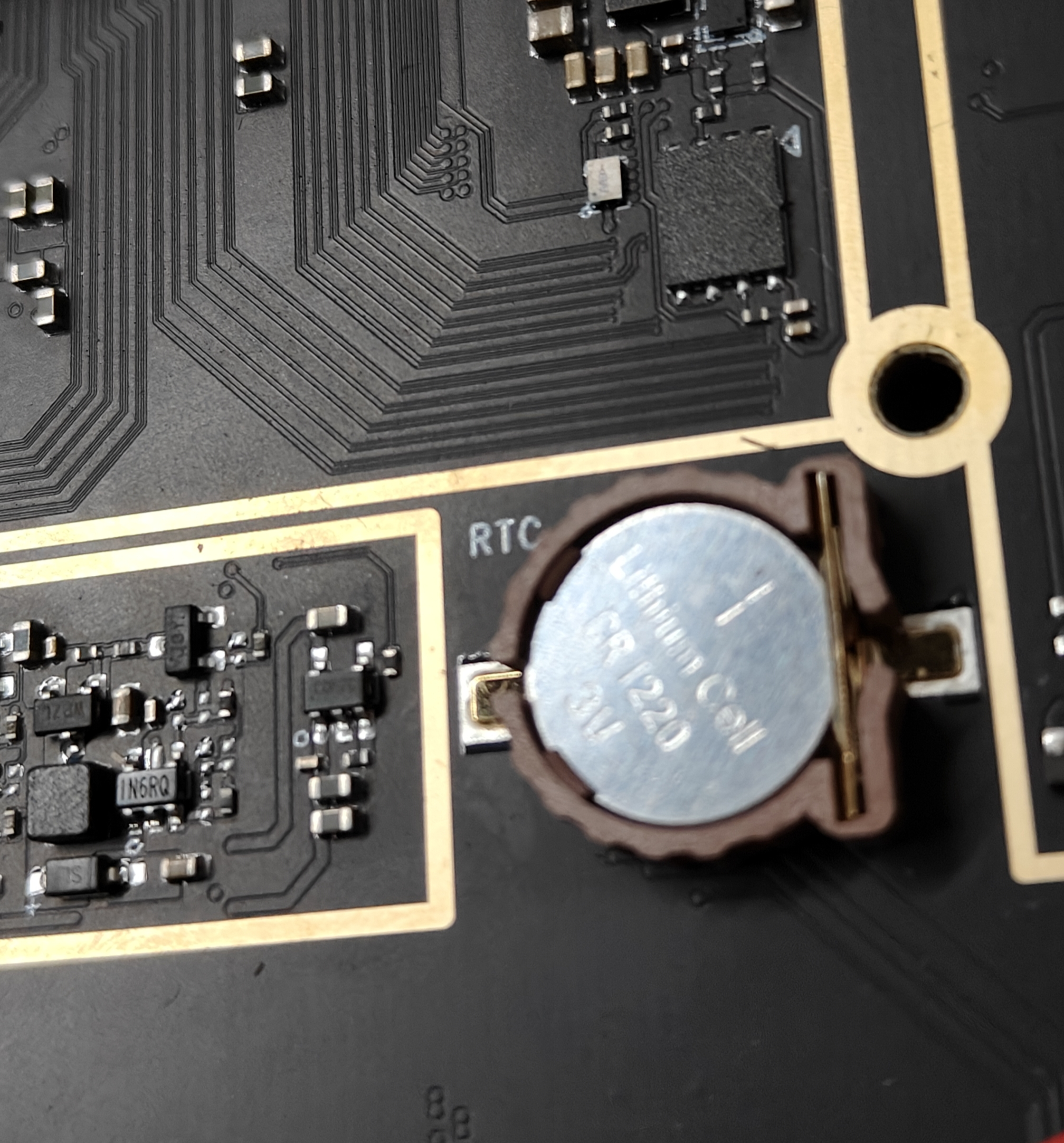
Install the RTC battery
Place the RTC battery in the Interface Description marked 23.
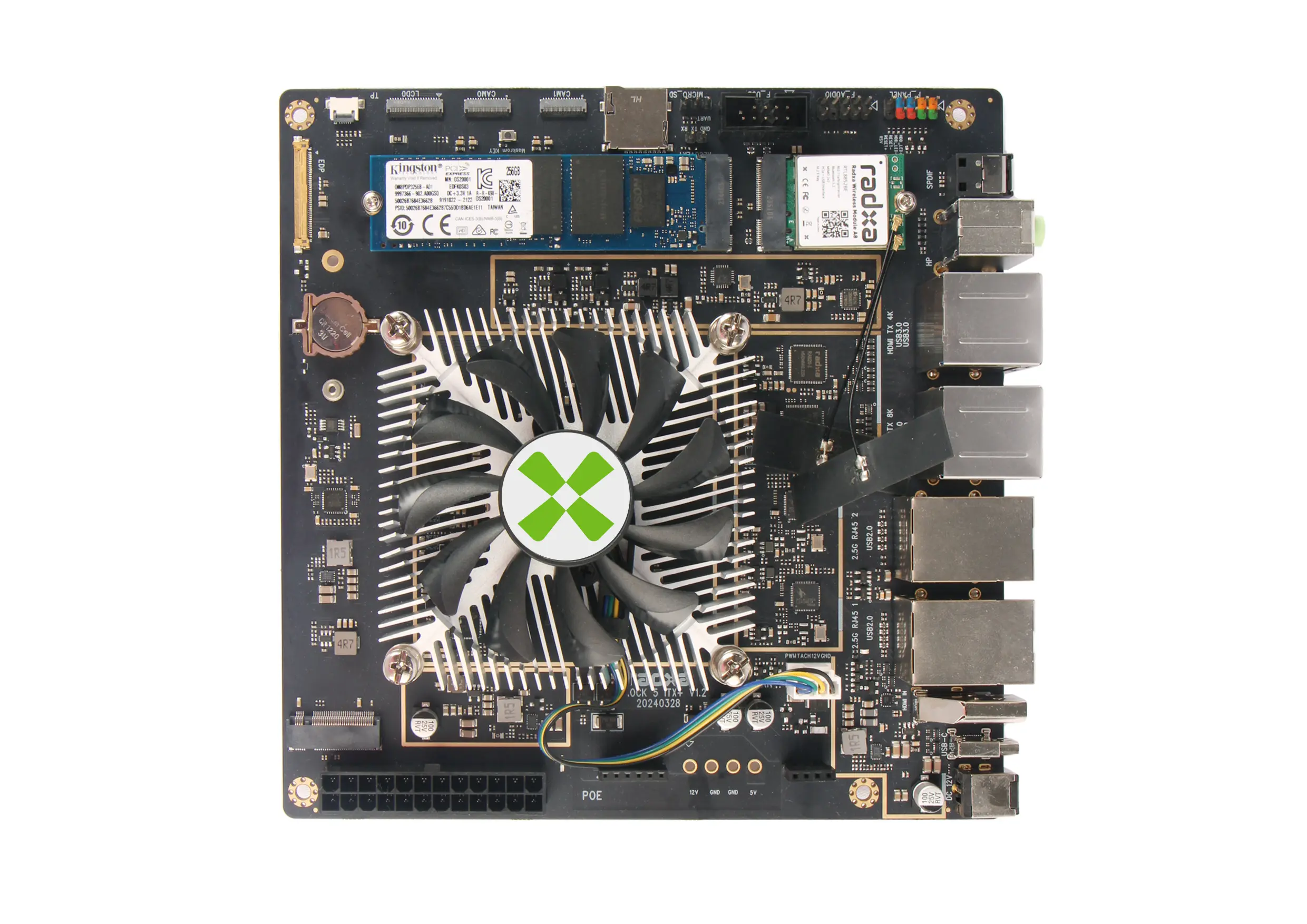
Install a cooling fan
- Firstly, apply the thermally conductive silicone grease evenly on the SoC RK3588, and then install the heat sink by aligning the four holes on it, please refer to the illustrated instructions for specific steps.
Please pay attention to the fan connector, which has an anti-reverse design.
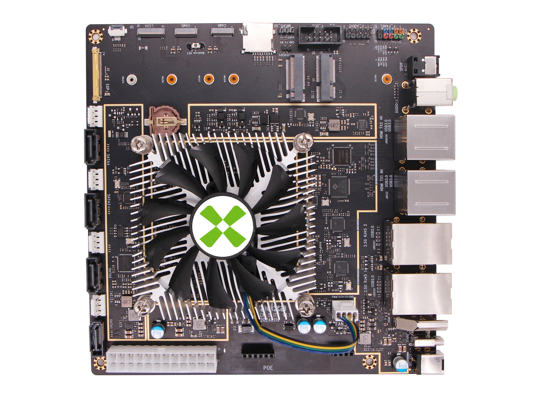
- Next, align the fasteners precisely with the four holes on the back of the ROCK 5 ITX motherboard to ensure a flawless installation.
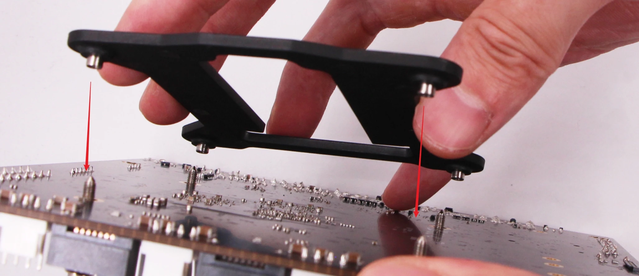
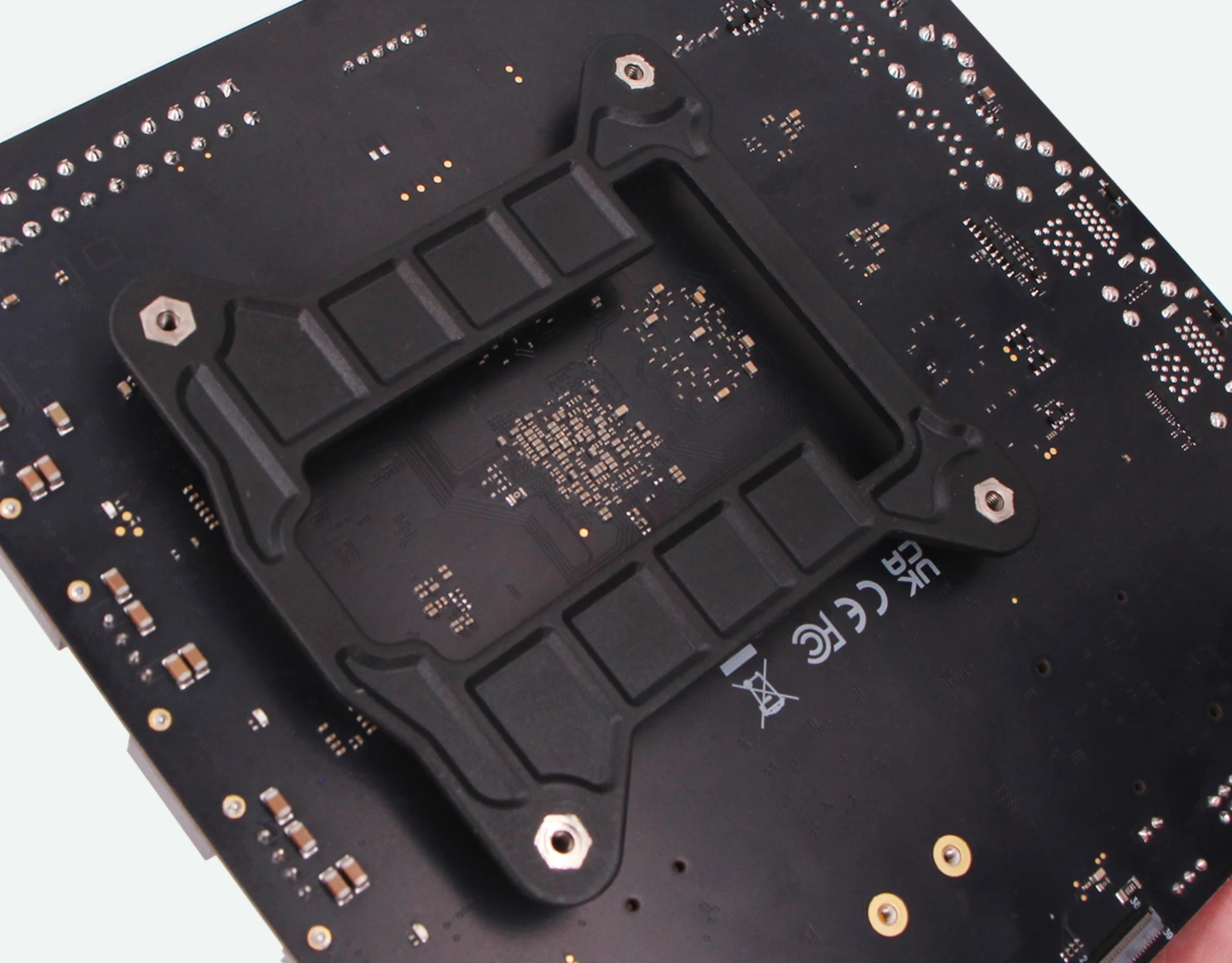
- Finally, please tighten the screws in diagonal order to secure the heat sink, this will effectively prevent damage to the ROCK 5 ITX motherboard during the securing process.
Install the SSD and WIFI-BT Module
Insert the SSD into the Interface Description labelled 26, then insert the WIFI-BT module into the Interface Description labelled 27, and finally fix it with screws.
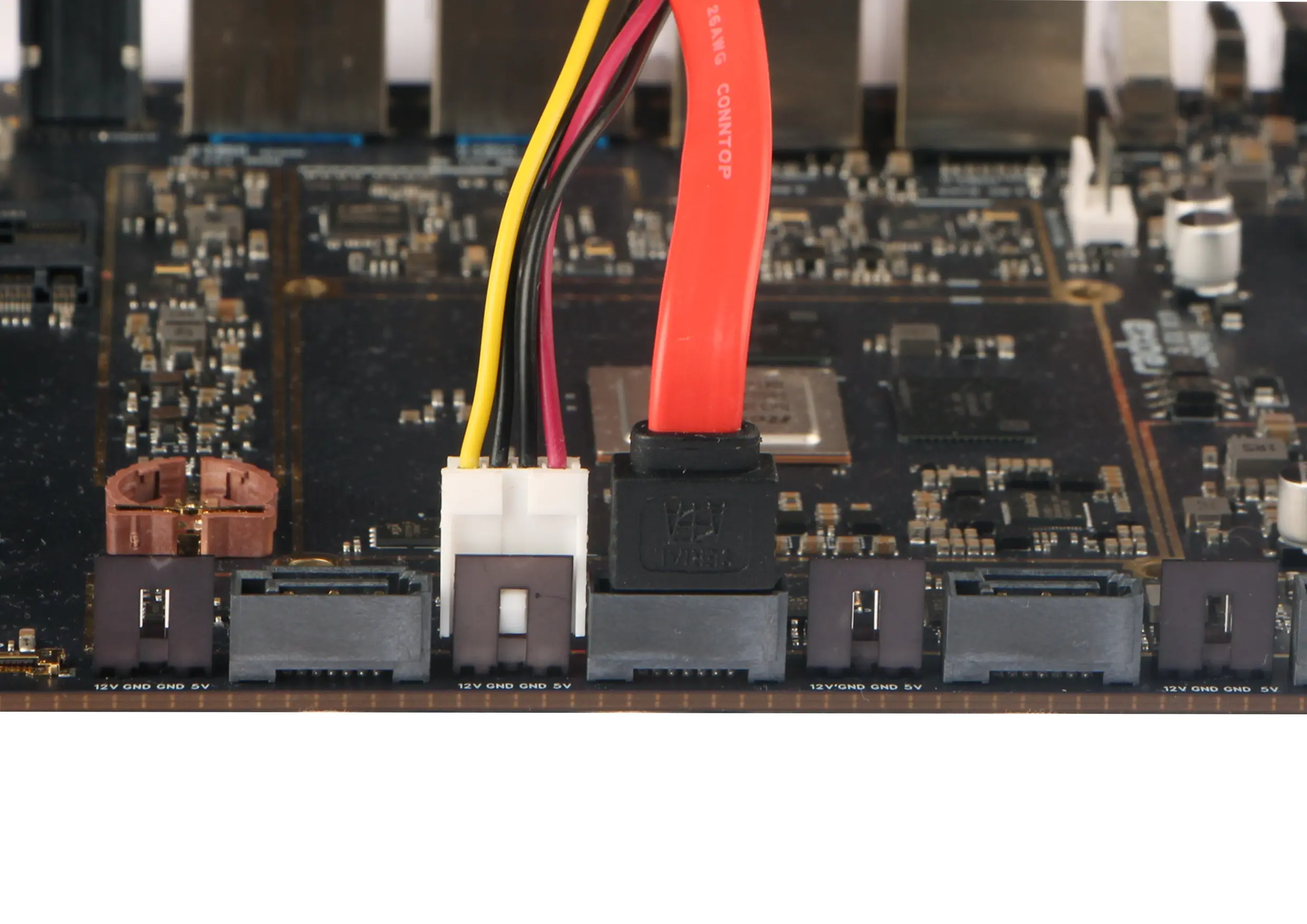
Install the SATA Hard Drive
If the motherboard has a SATA 3.0 interface, wire it as follows.
The upper one in the picture below is the data cable. Plug this cable into one of the cables labelled 20 in Interface Description.
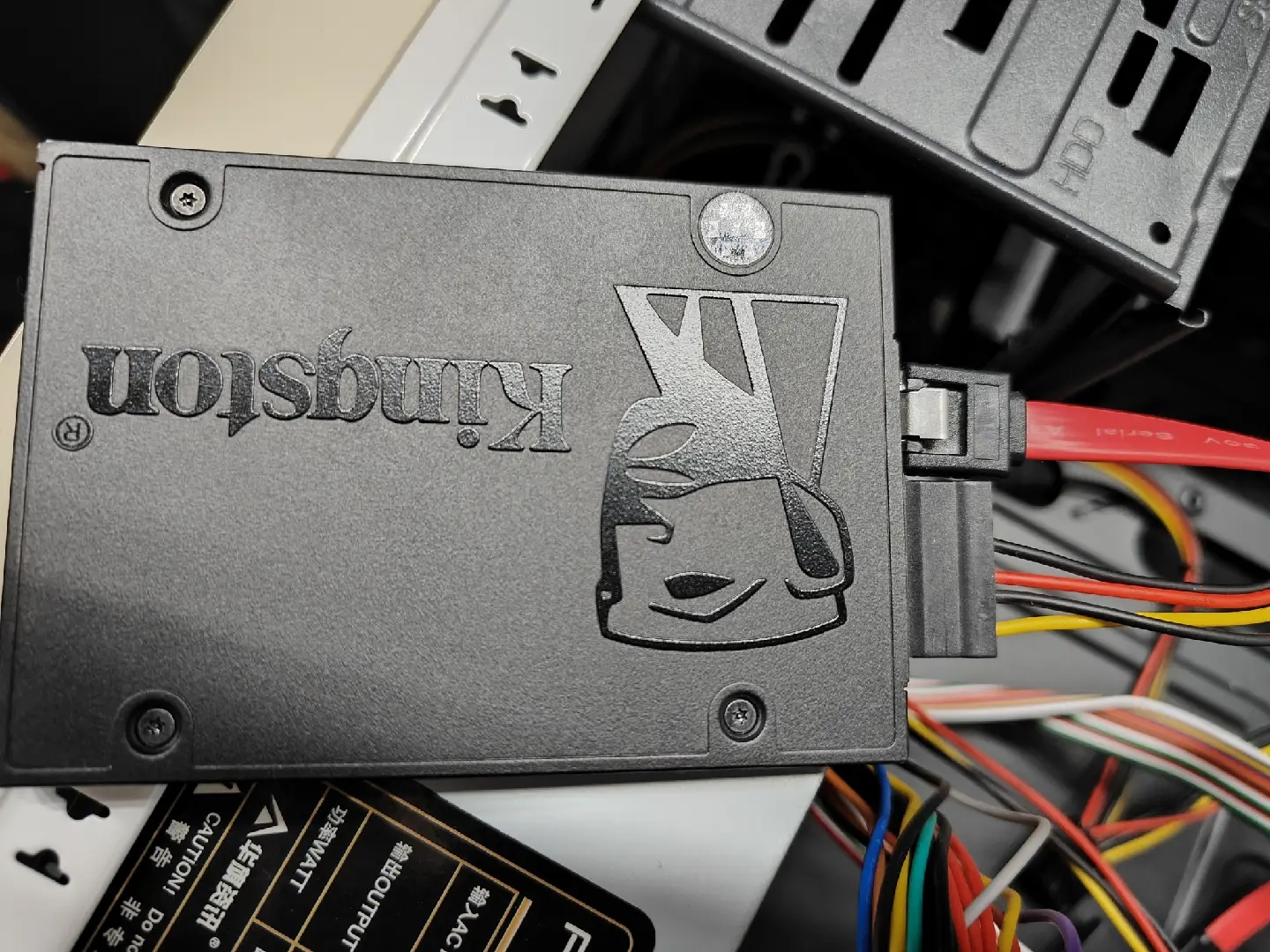
If there is a SATA power cable in the chassis, just plug the SATA power cable into the SATA disc, and just let the number 21 in Interface Description empty.
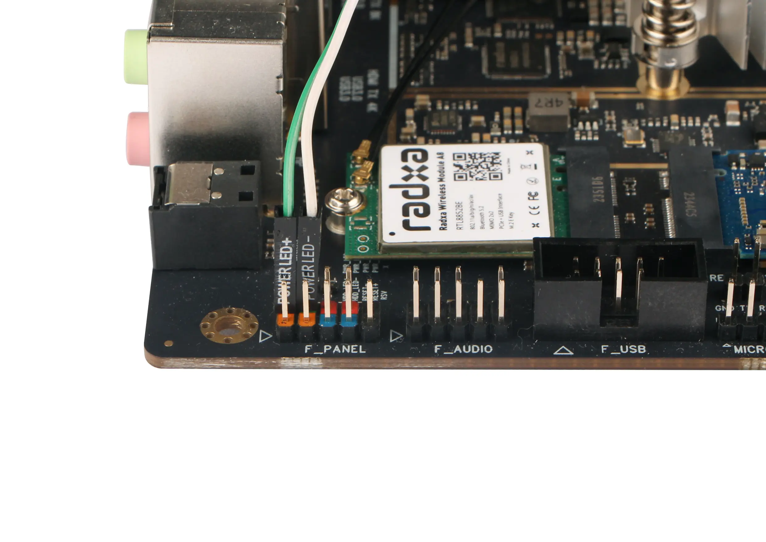
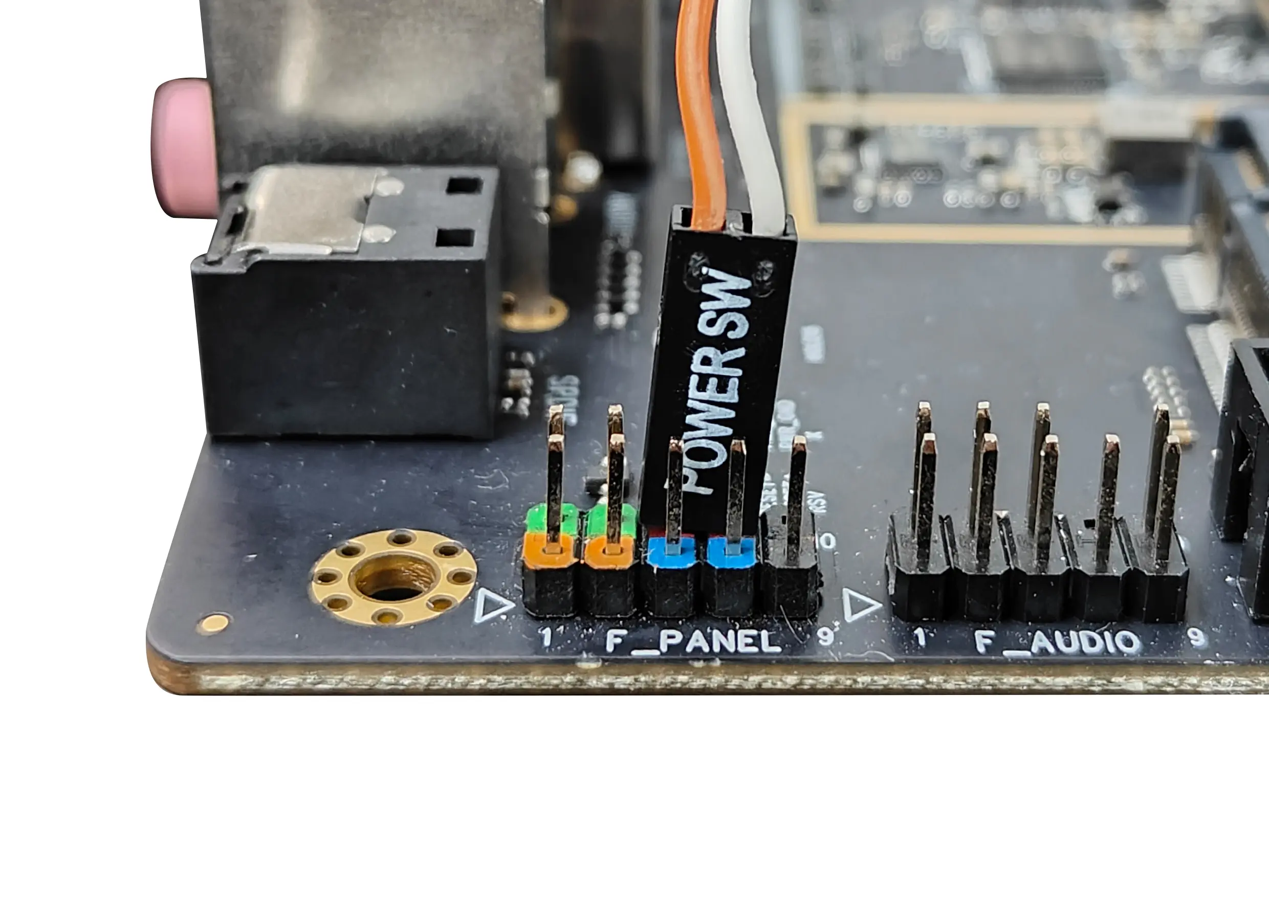
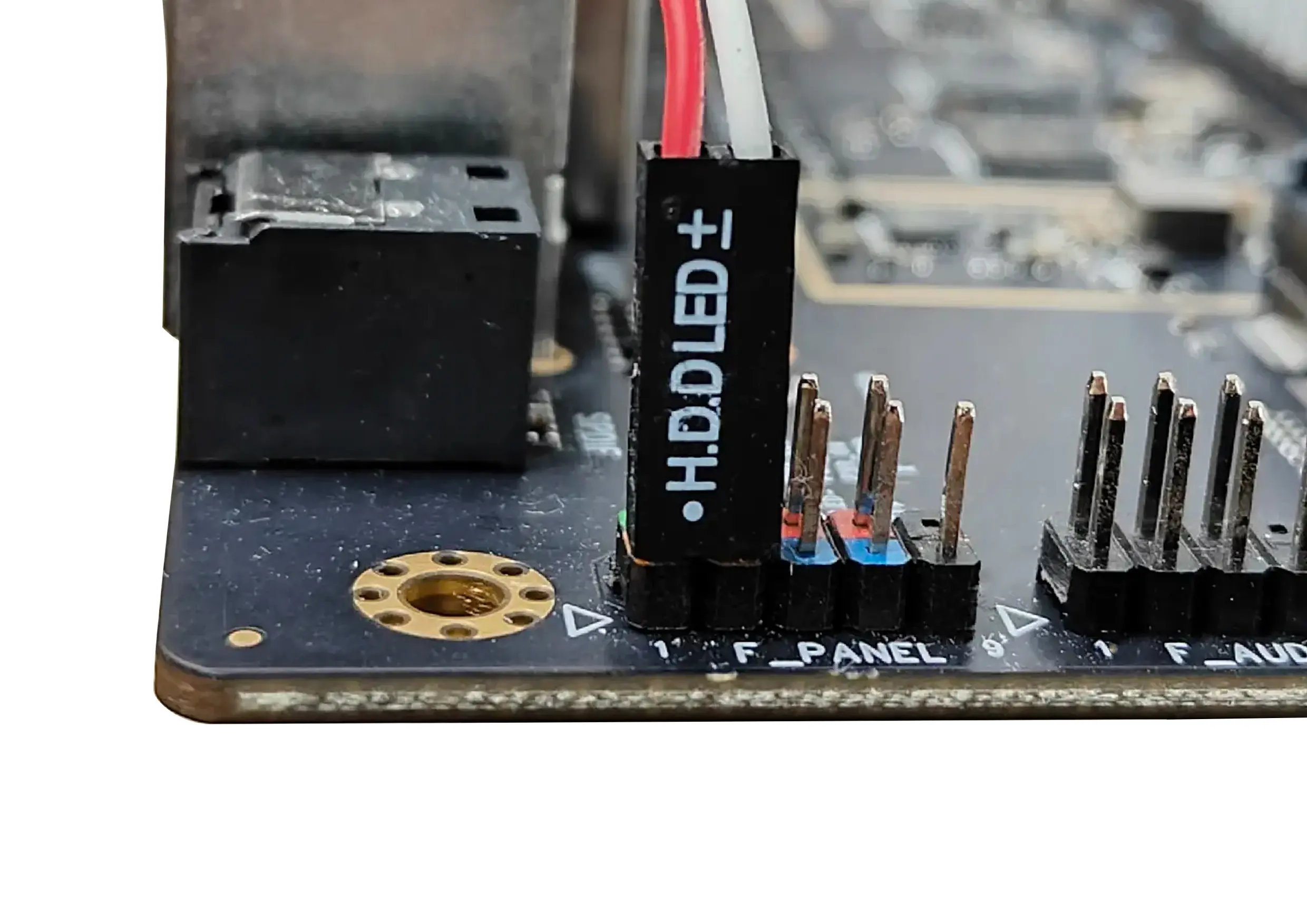
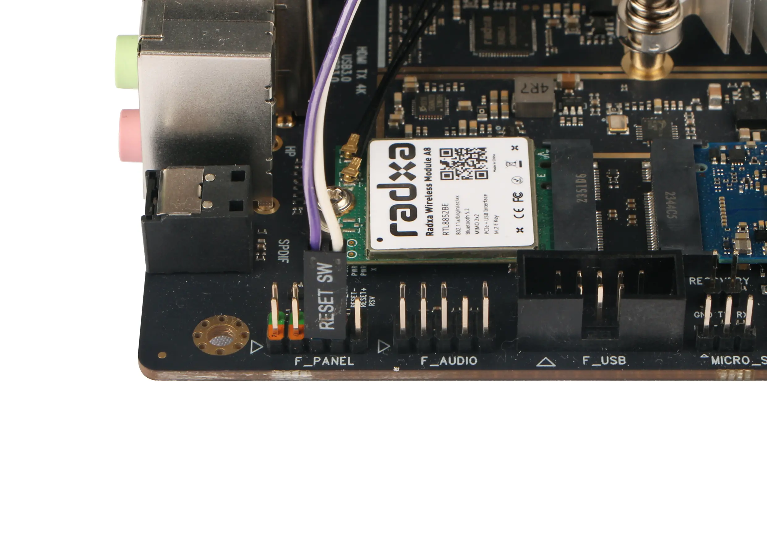
Install the F_PANEL cable
Insert F_PANEL into labelled 8 in Interface Description in marker 8.
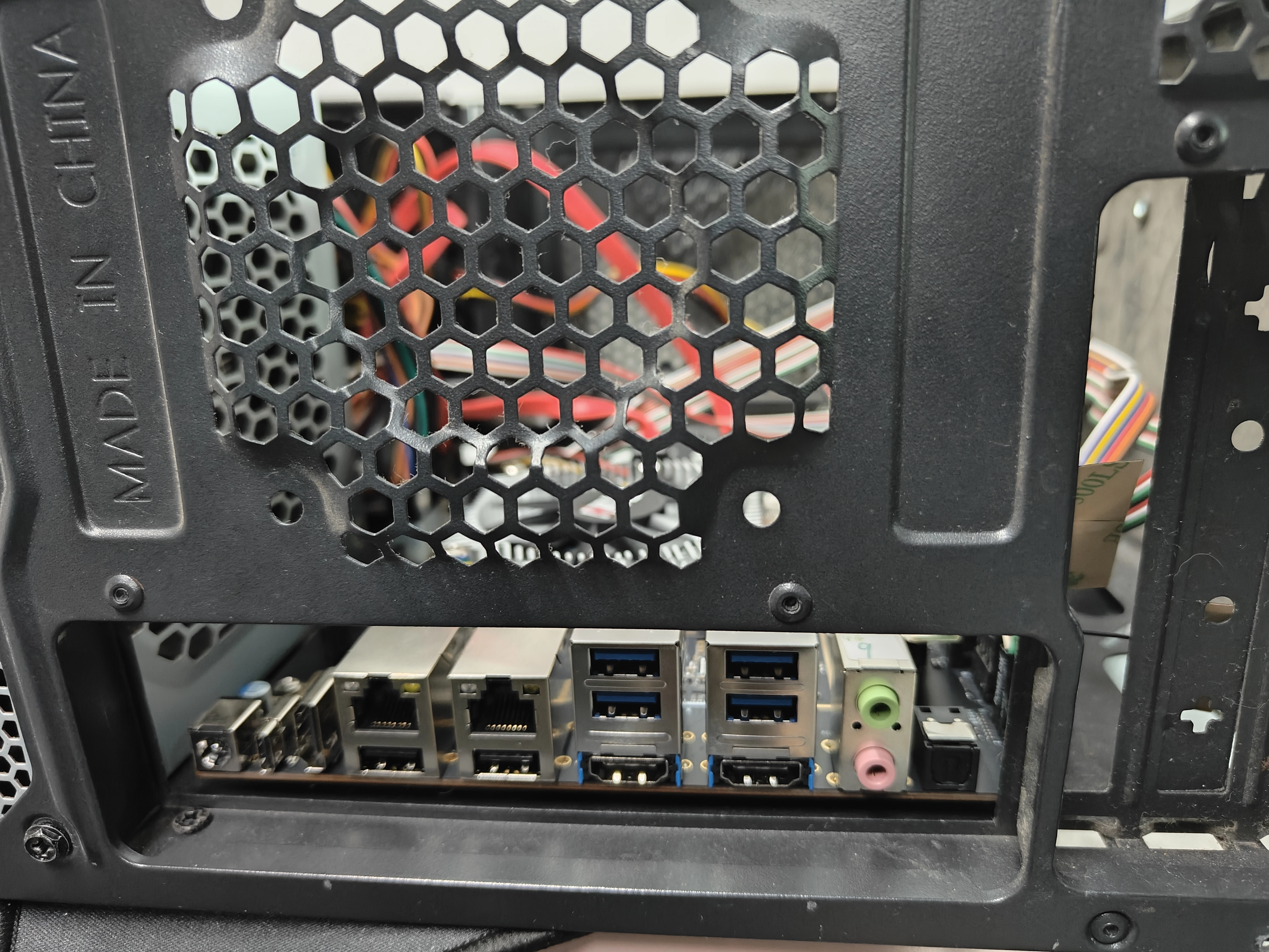
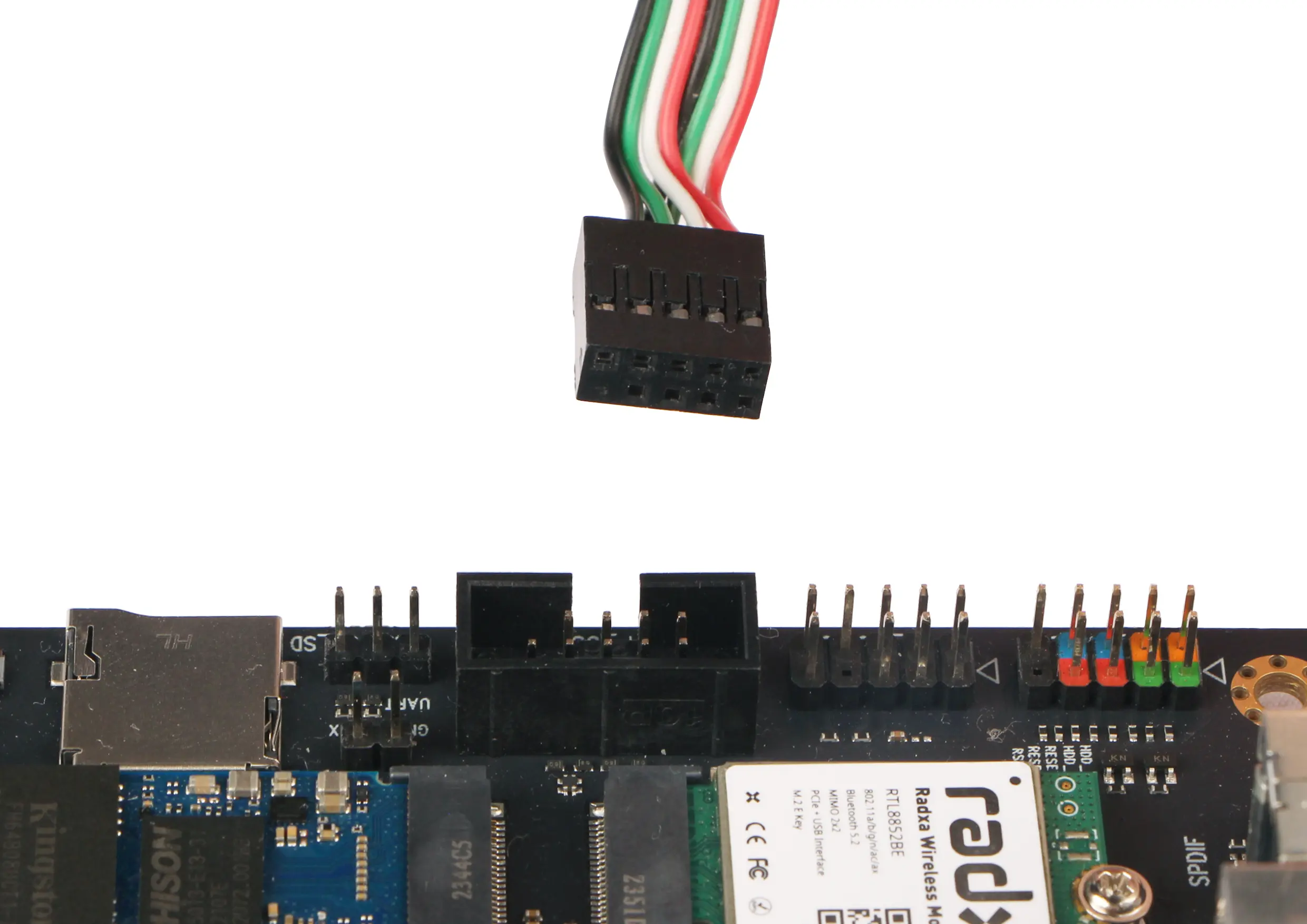
Install F_USB cable
Insert the F_USB cable into mark 6 in Interface description in mark 6.
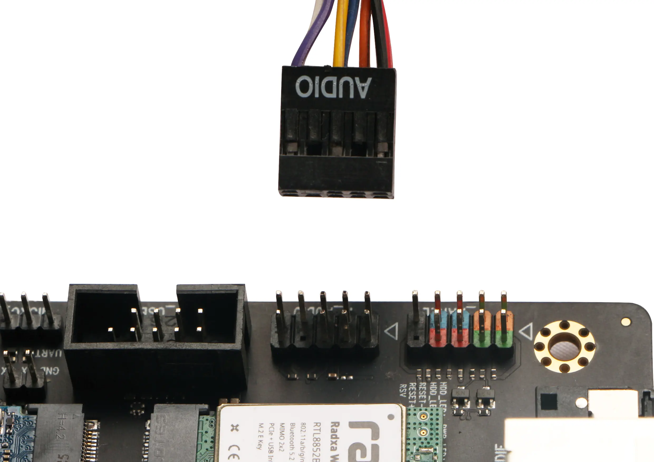
Install the F_AUDIO cable
Insert F_AUDIO into interface description at mark 7.
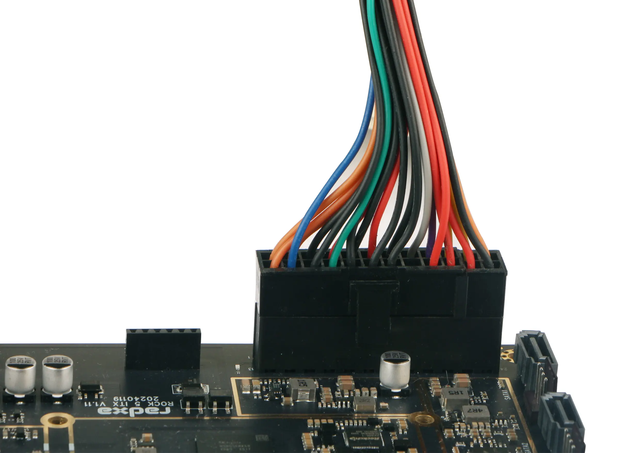
Install the ATX Power
Insert the ATX Power cable into the ATX POWER cable slot as shown below.
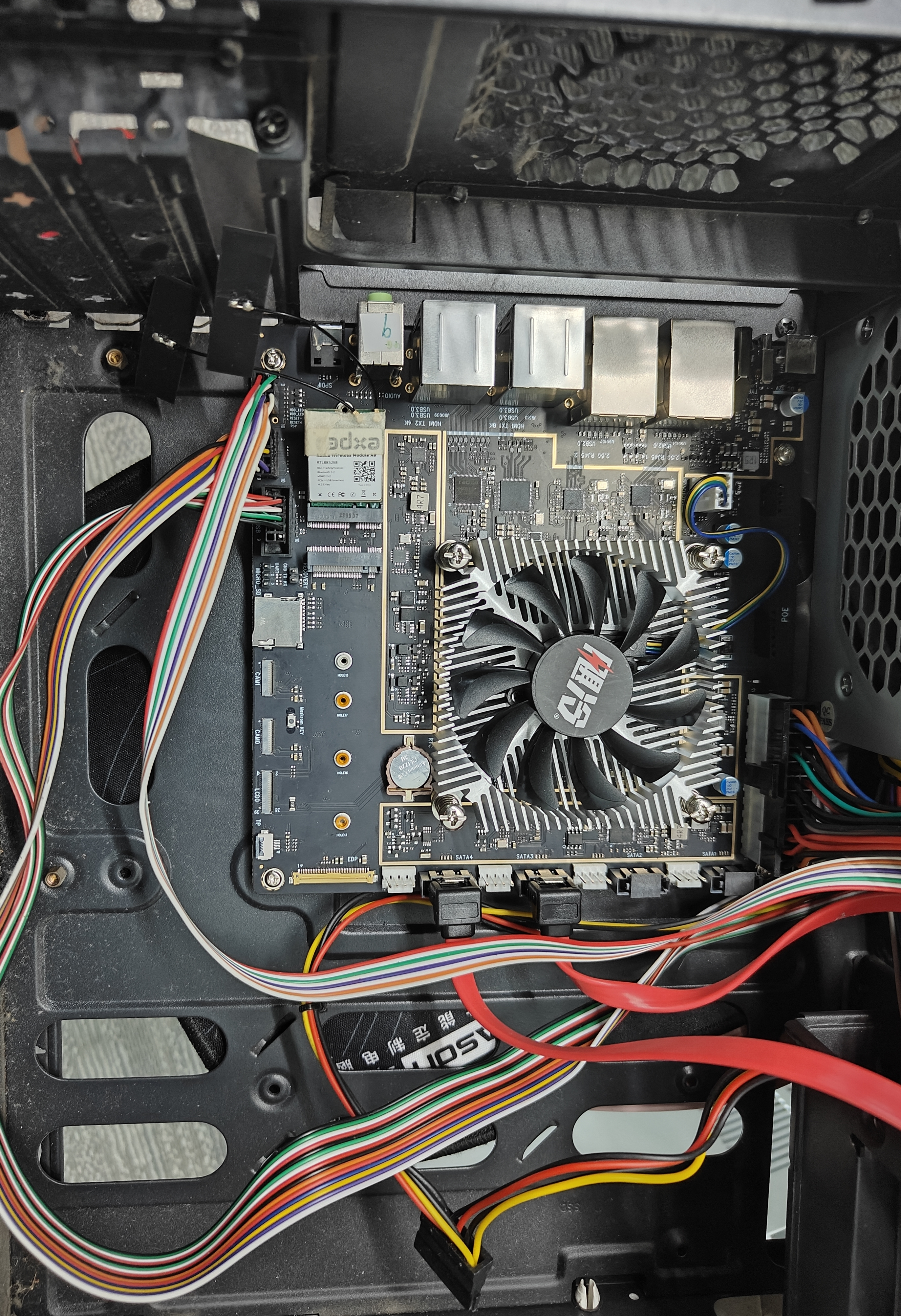
Securing the motherboard
Secure the motherboard to the bottom of the chassis.