Using M.2 SATA breakout board on ROCK 5A
When you use M2.E to SATA breakout board, you need to prepare a SATA data cable for connecting with SATA hard disk and a SATA Power Splitter Cable for SATA power supply.
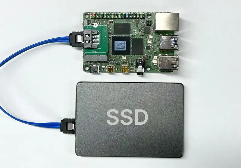
As shown in the figure, connect the M.2 E key to SATA breakout board to the M2.E port of RKCK 5A, and then use the SATA data cable to connect ROCK 5A and SATA SSD.
The red GPIO of Radxa's SBCs can be used for 5V power supply for SATA, and the black GPIO is usually used for GND.
After you install, you need to enable SATA.
Press "Ctrl + Alt + T" simultaneously to open a terminal, run rsetup command as below:
radxa@rock-5a:~$ rsetup
Typing the password and select Overlays to rsetup tool interface.
Select Overlays:
Configure Device Tree Overlay
        Manage overlays
        View overlay info
        Install overlay from source
        Reset overlays
        <Ok>             <Cancel>
Then, select Manage overlays:
Configure Device Tree Overlay
        Manage overlays
        View overlay info
        Install overlay from source
        Reset overlays


      <Ok>            <Cancel>
Next, the installed device tree would shown, it may be different on different product.
Press the space bar to Enable SATA0
Please select overlays:
        [ ] Enable 1-Wire on GPIO4_B1
        [ ] Enable FIQ Debugger on UART4-M2
        [ ] Enable FIQ Debugger on UART6-M1
        [ ] Enable FIQ Debugger on UART7-M2
        [ ] Enable FIQ Debugger on UART8-M0
        [ ] Enable I2C1-M0
        [ ] Enable I2C2-M4
        [ ] Enable I2C4-M3
        [ ] Enable I2C6-M0
        [ ] Enable I2C6-M3
        [ ] Enable I2C7-M3
        [ ] Enable PWM0-M2
        [ ] Enable PWM1-M2
        [ ] Enable PWM11-M1
        [ ] Enable PWM14-M1
        [ ] Enable PWM14-M2
        [ ] Enable PWM15-M1
        [ ] Enable PWM15-M3
        [ ] Enable PWM6-M0
        [ ] Enable PWM7-M0
        [ ] Enable Radxa Camera 4K
        [ ] Enable Radxa Display 10HD
        [ ] Enable Radxa Display 8HD
        [ ] Enable Raspberry Pi Camera V2
        [ ] Enable SATA0
        [ ] Enable UART2-M0
        [ ] Enable UART2-M2
        [ ] Enable UART3-M1
        [ ] Enable UART4-M2
        [ ] Enable UART6-M1
        [ ] Enable UART7-M1
        [ ] Enable UART7-M1 with Hardware Flow Control
        [ ] Enable UART7-M2
        [ ] Enable UART8-M0
        [ ] Enable spidev on SPI0-M1 over CS0
        [ ] Enable spidev on SPI0-M2 over CS0
        [ ] Enable spidev on SPI4-M2 over CS0
        [ ] Set OTG port to Host modeq
        [ ] Set OTG port to Peripheral mode
        <Ok>                   <Cancel>
Select the overlays you want to load with the space bar,
[*] Enable SATA0
Overlay with a * indicates that it is enabled. It would work after reboot.
Check whether the SATA mount is successful
You can check whether the SSD card is recognized by lsblk.
radxa@rock-5a:~$ lsblk
NAME         MAJ:MIN RM   SIZE RO TYPE MOUNTPOINT
sda            8:0    0 476.9G  0 disk
mmcblk0      179:0    0  14.5G  0 disk
├─mmcblk0p1  179:1    0    16M  0 part /config
└─mmcblk0p2  179:2    0  14.4G  0 part /
mmcblk0boot0 179:32   0     4M  1 disk
mmcblk0boot1 179:64   0     4M  1 disk
zram0        254:0    0   3.9G  0 disk [SWAP]
As you can see, the system has recognized the SATA (sda).