Overview
The Radxa ROCK 5 Model A (ROCK 5A) is a Single Board Computer (SBC) in a compact form factor packed with a wide range of class-leading functionality, features and expansion options. The ROCK 5A is an ideal choice for makers, IoT enthusiasts, hobbyists, gamers, PC users and everyone who need an extremely highly specified platform with outstanding performance and reliability. Radxa offers the ROCK 5A board in various LPDDR4x RAM memory options:
4GB
8GB
16GB
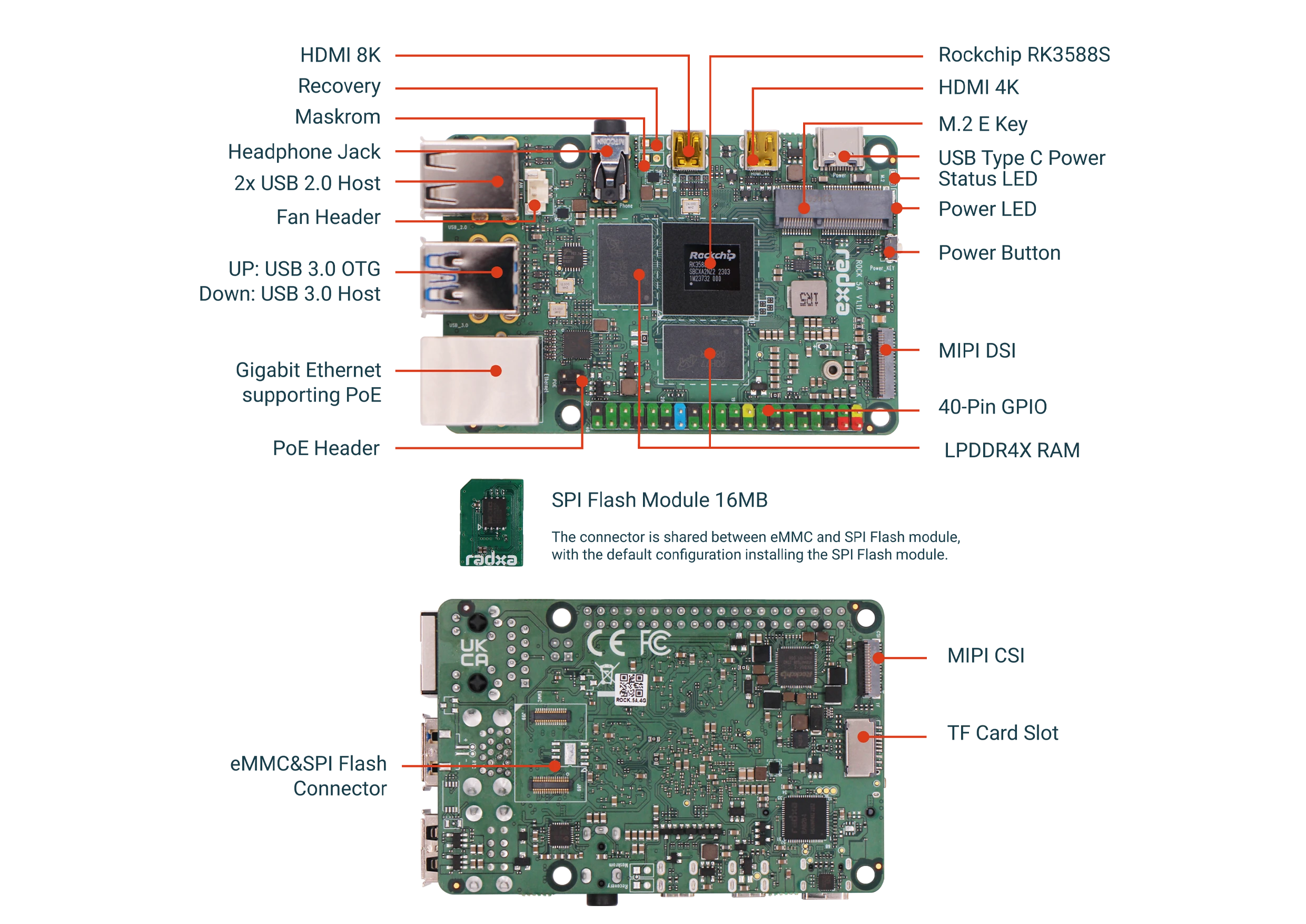
Note: The actual board layout or components location may change during the time but the main connectors type and location will remain the same
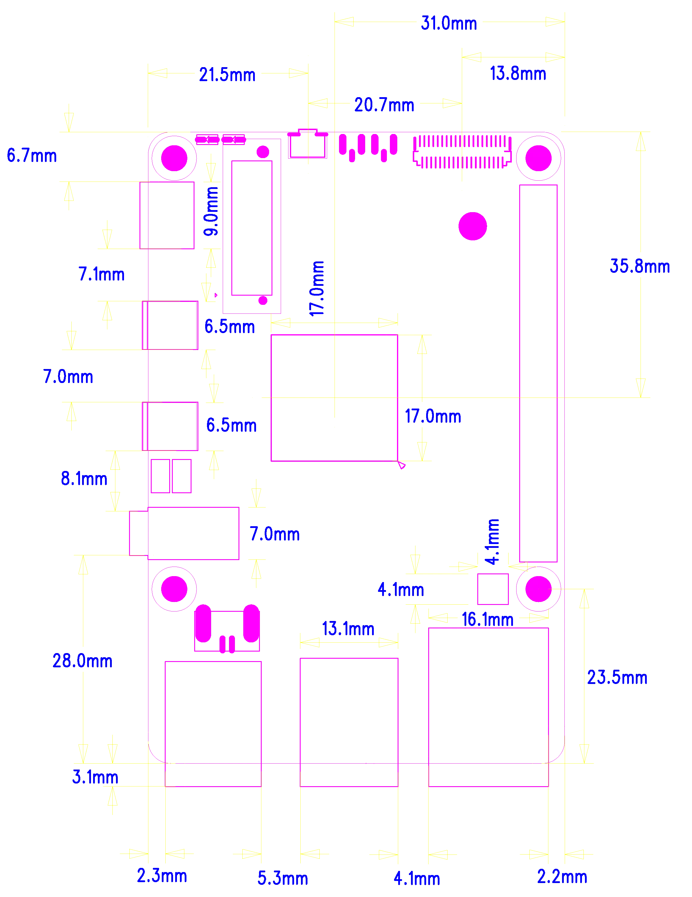
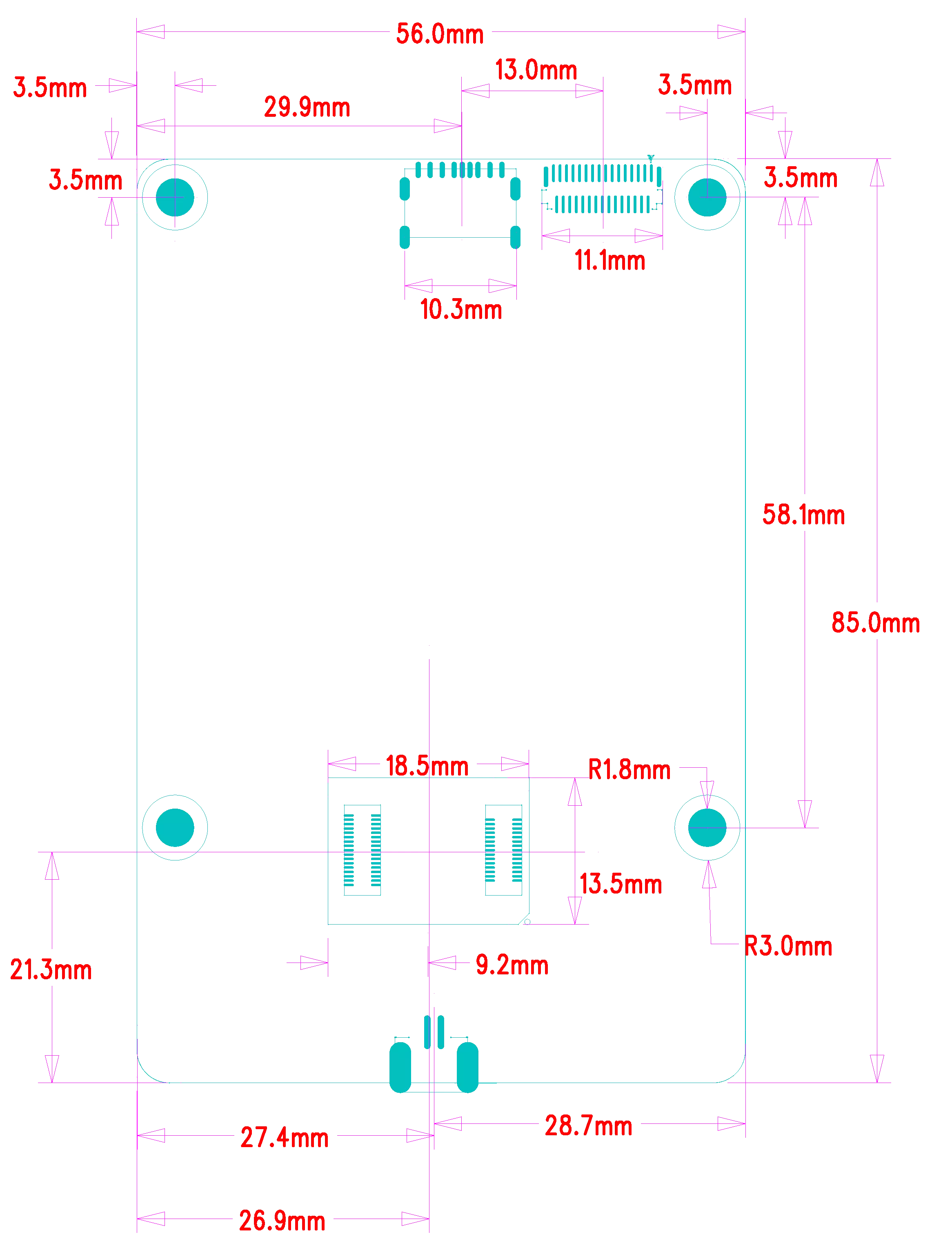
Mechanical Specification
Electrical Specification
Power Requirements
The ROCK 5A supports various power supply technologies including smart power adapter as well as fixed voltage:
- USB Type-C™ PD Version 2.0 with 9V/2A, 12V/2A, 15V/2A and 20V/2A.
- Qualcomm® Quick Charge™ 2.0 QC 3.0/2.0 adapter, 9V/2A, 12V/2A
- Power adapter with fixed voltage in 5.2V to 20V range on the USB Type-C port
- 5V Power applied to the GPIO PIN 2 & 4
The recommended power source should be able to produce, at least, 24W without a M.2 SSD or 30W with a M.2 SSD.
GPIO Voltage
| GPIO | Voltage Level | Tolerance |
|---|---|---|
| All GPIO | 3.3V | 3.63V |
| SARADC_IN5 | 3.3V | 3.3V |
ROCK 5A eMMC Tutorial
When you receive the ROCK 5A, the ROCK 5A is installed with SPI Flash, you need to remove the SPI Flash before you can install the eMMC. eMMC uses a B2B connector, just align it with the B2B connection connector of the ROCK 5A and install it. As shown in the picture:
Maskrom mode
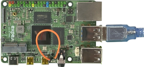
The OTG connector of the ROCK 5A is located on the upper USB 3.0 connector and can be used to communicate with the host computer and the board in Maskrom via a USB-A to USB-A cable.
To enter Maskrom mode on the ROCK 5A, proceed as follows:
- unplug the power cable and power off
- Connect the Maskrom pin, which is located between the HDMI and headphone ports, marked 23
- Plug in the power cable and power up the board, if the green light is on, you have successfully entered Maskrom mode
- Connect the OTG port of the board and the USB 3.0 port of the host PC via the USB-A to USB-A cable for communication
Operating Conditions
The ROCK 5A has been designed to operate between 0°C to 50°C.
This temperature range was defined based on typical usage where the efficient use of Arm big.LITTLE technology can automatically select which processor core to utilise for a given task, the result of which is minimal heat generation and responsive user experience.
The ROCK 5A is built on a high‑performance mobile chipset which is designed to operate for extended durations on batteries with efficiency at its core. As with all electronic devices heat is a by‑product of operation which increases with performance and workload; during basic use cases such as web browsing, editing text or listening to music the SoC will automatically select the smallest processors available or dedicated hardware accelerators to reduce heat generation thus reserving the higher performance processors and thermal window for demanding tasks as and when required.
The SoC (RK3588S) is specified to limit its maximum internal temperature to 80°C before throttling the clock speeds to maintain reliability within the allowed temperature range. If the ROCK 5A is intended to be used continuously in high performance applications, it may be necessary to use external cooling methods (for example, heat sink, fan, etc.) which will allow the SoC to continue running at maximum clock speed indefinitely below its predefined 80°C peak temperature limiter.