40-PIN Functional Testing
GPIO
GPIO Introduction
General Purpose Inputs/Outputs (GPIOs) are non-dedicated digital signal pins on the circuit board of an integrated circuit or electronic circuit (e.g., MCU/MPU) that can be used as inputs or outputs, or both, and can be controlled by software.
Preparations
- One Radxa ROCK 5A
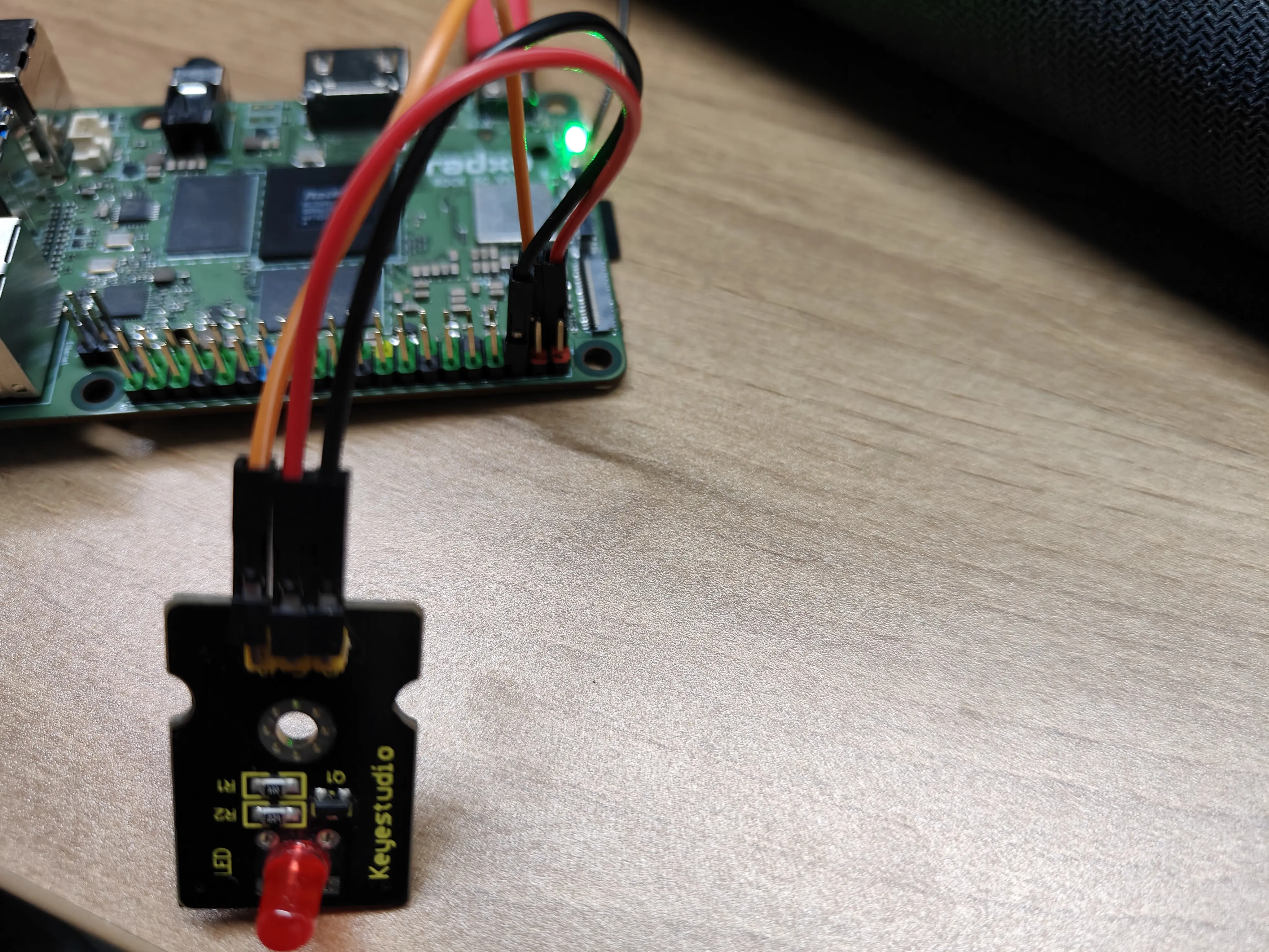
- One LED
Connection
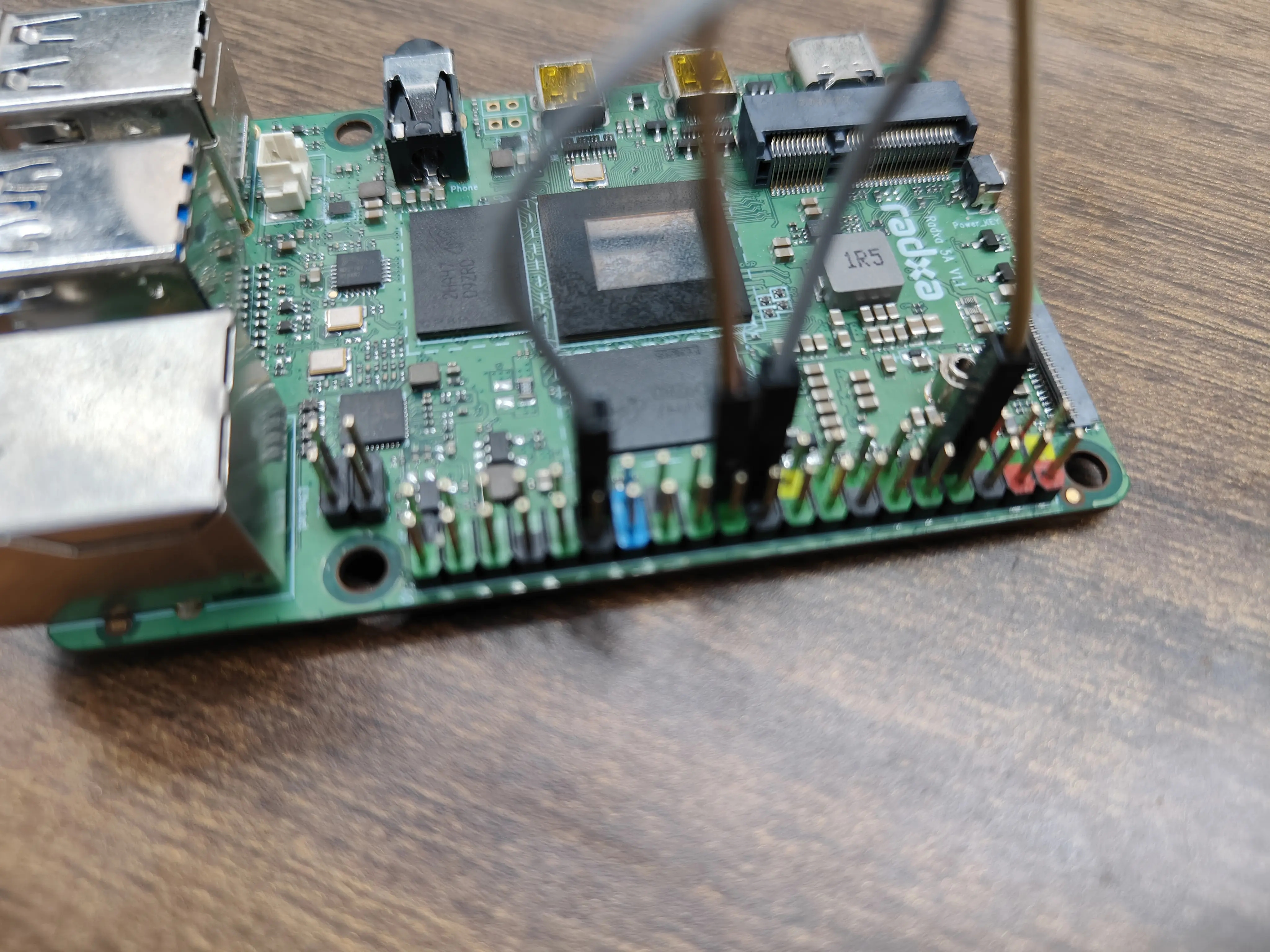
Connecting PIN_3 of Radxa ROCK 5A as shown
Test
Input Tests
Ground 3 or connect to 3.3V,
radxa@rock-5a:~$ gpioget gpiochip1 31
This command outputs 0 if ground is connected and 1 if 3.3V is connected.
Output Test
  radxa@rock-5a:~$ sudo gpioset -m signal $(sudo gpiofind PIN_3)=0 # Output low, Led off
  radxa@rock-5a:~$ sudo gpioset -m signal $(sudo gpiofind PIN_3)=1 # Output high, Led on
The same GPIO cannot be used by two processes at the same time, otherwise it will indicate resource usage. Therefore, you need to wait for the first command to finish executing before you can execute the second command.
I2C
I2C Introduction
I2C (Inter-Integrated Circuit; pronounced "eye-squared-see" or "eye-two-see"), also known as I2C or IIC, is a synchronous, multi-controller/multi-destination (historically known as master/slave), single-ended, serial communications bus invented by Philips Semiconductors in 1982.
Preparations
- One Radxa ROCK 5A
- One OLED
Enable Overlay
Please refer to Device Tree Configuration to enable I2C Related Overlay, eg: "Enable I2C8-M2".
Connection
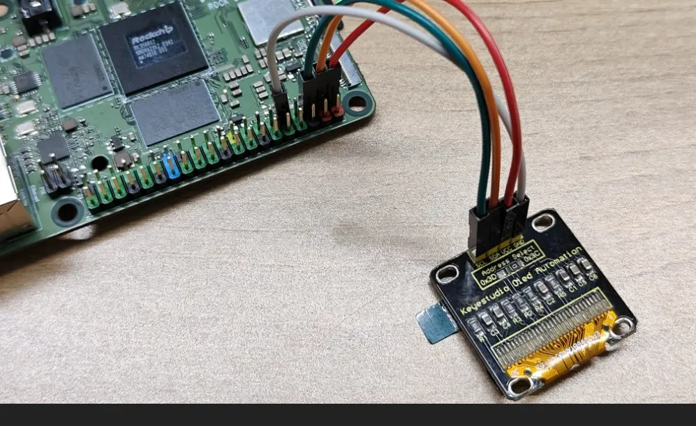
Connect Radxa ROCK 5A and OLED as follows
| Radxa ROCK 5A | <--> | OLED |
|---|---|---|
| PIN_5 | <--> | SCL |
| PIN_3 | <--> | SDA |
| PIN_1 | <--> | VCC |
| PIN_9 | <--> | GND |
Test
-
Open a terminal and install the Python library python3-periphery by typing the following command in the terminal
-
Create a new Python file called Oled.py and paste the following code into it:
Oled.py
from periphery import I2C
import time

I2C_ADDR = 0x3c
I2C_BUS = "/dev/i2c-8"

i2c = I2C(I2C_BUS)

# SSD1306 init_cmds
init_cmds = [
    0xAE,  # Display off
    0x00,  # Set lower column address
    0x10,  # Set higher column address
    0x40,  # Set display start line
    0xB0,  # Set page address
    0x81,  # Set contrast control
    0xCF,
    0xA1,  # Set segment remap
    0xA6,  # Normal display
    0xA8,  # Set multiplex ratio
    0x3F,
    0xC8,  # Set COM output scan direction
    0xD3,  # Set display offset
    0x00,
    0xD5,  # Set display clock divide ratio/oscillator frequency
    0x80,
    0xD9,  # Set pre-charge period
    0xF1,
    0xDA,  # Set COM pins hardware configuration
    0x12,
    0xDB,  # Set VCOMH deselect level
    0x40,
    0x8D,  # Enable charge pump regulator
    0x14,
    0xAF   # Display on
]

for cmd in init_cmds:
    i2c.transfer(I2C_ADDR, [I2C.Message([0x00, cmd])])

def oled_clear():
    for page in range(8):
        i2c.transfer(I2C_ADDR, [I2C.Message([0x00, 0xB0 + page])])
        i2c.transfer(I2C_ADDR, [I2C.Message([0x00, 0x00])])
        i2c.transfer(I2C_ADDR, [I2C.Message([0x00, 0x10])])
        for _ in range(128):
            i2c.transfer(I2C_ADDR, [I2C.Message([0x40, 0x00])])

char_map = {
    "H": [0x00, 0x7F, 0x08, 0x08, 0x08, 0x7F,],
    "R": [0x00, 0x7F, 0x09, 0x19, 0x29, 0x46],
    "e": [0x00, 0x38, 0x54, 0x54, 0x54, 0x18],
    "l": [0x00, 0x00, 0x41, 0x7F, 0x40, 0x00],
    "o": [0x00, 0x38, 0x44, 0x44, 0x44, 0x38],
    "r": [0x00, 0x7C, 0x08, 0x04, 0x04, 0x08],
    "a": [0x00, 0x20, 0x54, 0x54, 0x54, 0x78],
    "d": [0x00, 0x38, 0x44, 0x44, 0x48, 0x7F],
    "x": [0x00, 0x44, 0x28, 0x10, 0x28, 0x44]
}

def string_to_bytes(string):
    bytes_list = []
    for char in string:
        bytes_list.extend(char_map.get(char, [0x00] * 4))
        bytes_list.append(0x00)
    return bytes_list

oled_clear()
hello_world_bytes = string_to_bytes("Hello Radxa")
i2c.transfer(I2C_ADDR, [I2C.Message([0x00, 0xB0])])
i2c.transfer(I2C_ADDR, [I2C.Message([0x00, 0x00])])
i2c.transfer(I2C_ADDR, [I2C.Message([0x00, 0x10])])
for byte in hello_world_bytes:
    i2c.transfer(I2C_ADDR, [I2C.Message([0x40, byte])])

i2c.close()
This script is only an example, you need to modify the variable I2C_BUS according to the actual situation.
:::.
- In a terminal, execute the following command to test
sudo python3 Oled.py
After executing the above command, Oled will display the characters "Hello, Radxa".
PWM
PWM Introduction
Pulse Width Modulation (PWM) is a modulation technique that produces variable width pulses to represent the amplitude of an analog input signal. For high amplitude signals, the output switching transistor is on more of the time, while for low amplitude signals, the output switching transistor is off more of the time.
Preparations
- One Radxa ROCK 5A
- One LED
Enable Overlay
Please refer to DeviceTree configuration to enable PWM-related Overlay.
eg: "Enable PWM0_M2.
Connection
As shown in the picture,connect Radxa ROCK 5A's 23

Test
- Open a terminal and install the Python library for python3-periphery by typing the following command in the terminal
sudo apt-get install python3-periphery
- Create a new Python file called Pwm_led_test.py and paste the following code into the file:
Pwm_led_test.py
#!/usr/bin/env python3
# -- encoding: utf-8 --
from periphery import PWM
import time
step = 0.05
Range = int(1/0.05)
pwmchip = int(input("pwmchip:"))
channel = int(input("channel:"))
pwm = PWM(pwmchip, channel)
try:
pwm.frequency = 1e3
pwm.duty_cycle = 0.00
pwm.enable()
while True:
for i in range(0,Range):
time.sleep(step)
pwm.duty_cycle = round(pwm.duty_cycle+step,2)
if pwm.duty_cycle == 1.5:
time.sleep(1.5)
for i in range(0,Range):
time.sleep(step)
pwm.duty_cycle = round(pwm.duty_cycle-step,2)
except:
print("Error !\n")
finally:
pwm.duty_cycle = 1.0
pwm.close()
- In a terminal, execute the following command to test
  radxa@rock-5a:~$ sudo python3 Pwm_led_test.py
  pwmchip:0
  channel:0
After executing the above commands, Led will have a gradient effect (dark to light, light to dark).
SPI
Introduction to SPI
The Serial Peripheral Interface (SPI) is the de facto standard for synchronous serial communication (there are many variants), primarily used for short-range wired communication between integrated circuits in embedded systems.
Preparation
- One rock-5a
- One female-to-female Dupont wire
Enable Overlay
Please refer to
Device Tree configuration Enable SPIDEV Related Overlay, eg: "Enable spidev on SPI0-M2 over CS0"。
Connection
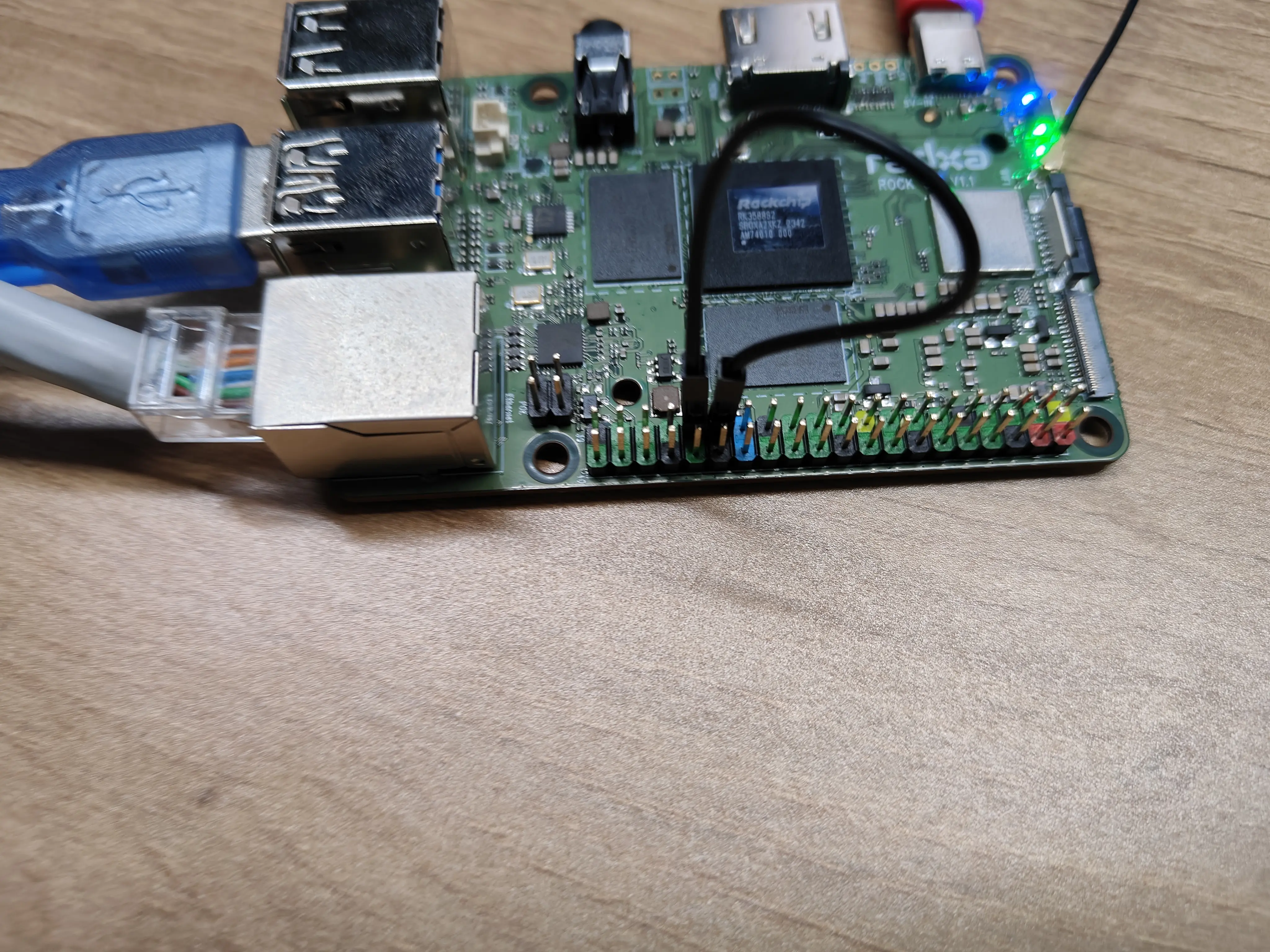
Short 29 and 31 as shown
Test
- Open a terminal and enter the following command in the terminal to install the compilation tool
sudo apt-get install build-essential
- Create a new C file called spidev_test.c and paste the following code into the file:
spidev_test.c
    /*
    * SPI testing utility (using spidev driver)
    *
    * Copyright (c) 2007  MontaVista Software, Inc.
    * Copyright (c) 2007  Anton Vorontsov <[email protected]>
    *
    * This program is free software; you can redistribute it and/or modify
    * it under the terms of the GNU General Public License as published by
    * the Free Software Foundation; either version 2 of the License.
    *
    * Cross-compile with cross-gcc -I/path/to/cross-kernel/include
    */

    #include <stdint.h>
    #include <unistd.h>
    #include <stdio.h>
    #include <stdlib.h>
    #include <string.h>
    #include <getopt.h>
    #include <fcntl.h>
    #include <sys/ioctl.h>
    #include <linux/ioctl.h>
    #include <sys/stat.h>
    #include <linux/types.h>
    #include <linux/spi/spidev.h>

    #define ARRAY_SIZE(a) (sizeof(a) / sizeof((a)[0]))

    static void pabort(const char *s)
    {
        perror(s);
        abort();
    }

    static const char *device = "/dev/spidev0.0";
    static uint32_t mode;
    static uint8_t bits = 8;
    static char *input_file;
    static char *output_file;
    static uint32_t speed = 500000;
    static uint16_t delay;
    static int verbose;

    uint8_t default_tx[] = {
        0xFF, 0xFF, 0xFF, 0xFF, 0xFF, 0xFF,
        0x40, 0x00, 0x00, 0x00, 0x00, 0x95,
        0xFF, 0xFF, 0xFF, 0xFF, 0xFF, 0xFF,
        0xFF, 0xFF, 0xFF, 0xFF, 0xFF, 0xFF,
        0xFF, 0xFF, 0xFF, 0xFF, 0xFF, 0xFF,
        0xF0, 0x0D,
    };

    uint8_t default_rx[ARRAY_SIZE(default_tx)] = {0, };
    char *input_tx;

    static void hex_dump(const void *src, size_t length, size_t line_size,
                char *prefix)
    {
        int i = 0;
        const unsigned char *address = src;
        const unsigned char *line = address;
        unsigned char c;

        printf("%s | ", prefix);
        while (length-- > 0) {
            printf("%02X ", *address++);
            if (!(++i % line_size) || (length == 0 && i % line_size)) {
                if (length == 0) {
                    while (i++ % line_size)
                        printf("__ ");
                }
                printf(" | ");  /* right close */
                while (line < address) {
                    c = *line++;
                    printf("%c", (c < 33 || c == 255) ? 0x2E : c);
                }
                printf("\n");
                if (length > 0)
                    printf("%s | ", prefix);
            }
        }
    }

    /*
    *  Unescape - process hexadecimal escape character
    *	  converts shell input "\x23" -> 0x23
    */
    static int unescape(char *_dst, char *_src)
    {
        int ret = 0;
        int match;
        char *src = _src;
        char *dst = _dst;
        unsigned int ch;

        while (*src) {
            if (*src == '\\' && *(src+1) == 'x') {
                match = sscanf(src + 2, "%2x", &ch);
                if (!match)
                    pabort("malformed input string");

                src += 4;
                *dst++ = (unsigned char)ch;
            } else {
                *dst++ = *src++;
            }
            ret++;
        }
        return ret;
    }

    static void transfer(int fd, uint8_t const *tx, uint8_t const *rx, size_t len)
    {
        int ret;
        int out_fd;
        struct spi_ioc_transfer tr = {
            .tx_buf = (unsigned long)tx,
            .rx_buf = (unsigned long)rx,
            .len = len,
            .delay_usecs = delay,
            .speed_hz = speed,
            .bits_per_word = bits,
        };

        if (mode & SPI_TX_QUAD)
            tr.tx_nbits = 4;
        else if (mode & SPI_TX_DUAL)
            tr.tx_nbits = 2;
        if (mode & SPI_RX_QUAD)
            tr.rx_nbits = 4;
        else if (mode & SPI_RX_DUAL)
            tr.rx_nbits = 2;
        if (!(mode & SPI_LOOP)) {
            if (mode & (SPI_TX_QUAD | SPI_TX_DUAL))
                tr.rx_buf = 0;
            else if (mode & (SPI_RX_QUAD | SPI_RX_DUAL))
                tr.tx_buf = 0;
        }

        ret = ioctl(fd, SPI_IOC_MESSAGE(1), &tr);
        if (ret < 1)
            pabort("can't send spi message");

        if (verbose)
            hex_dump(tx, len, 32, "TX");

        if (output_file) {
            out_fd = open(output_file, O_WRONLY | O_CREAT | O_TRUNC, 0666);
            if (out_fd < 0)
                pabort("could not open output file");

            ret = write(out_fd, rx, len);
            if (ret != len)
                pabort("not all bytes written to output file");

            close(out_fd);
        }

        if (verbose || !output_file)
            hex_dump(rx, len, 32, "RX");
    }

    static void print_usage(const char *prog)
    {
        printf("Usage: %s [-DsbdlHOLC3]\n", prog);
        puts("  -D --device   device to use (default /dev/spidev0.0)\n"
            "  -s --speed	max speed (Hz)\n"
            "  -d --delay	delay (usec)\n"
            "  -b --bpw	  bits per word\n"
            "  -i --input	input data from a file (e.g. \"test.bin\")\n"
            "  -o --output   output data to a file (e.g. \"results.bin\")\n"
            "  -l --loop	 loopback\n"
            "  -H --cpha	 clock phase\n"
            "  -O --cpol	 clock polarity\n"
            "  -L --lsb	  least significant bit first\n"
            "  -C --cs-high  chip select active high\n"
            "  -3 --3wire	SI/SO signals shared\n"
            "  -v --verbose  Verbose (show tx buffer)\n"
            "  -p			Send data (e.g. \"1234\\xde\\xad\")\n"
            "  -N --no-cs	no chip select\n"
            "  -R --ready	slave pulls low to pause\n"
            "  -2 --dual	 dual transfer\n"
            "  -4 --quad	 quad transfer\n");
        exit(1);
    }

    static void parse_opts(int argc, char *argv[])
    {
        while (1) {
            static const struct option lopts[] = {
                { "device",  1, 0, 'D' },
                { "speed",   1, 0, 's' },
                { "delay",   1, 0, 'd' },
                { "bpw",	 1, 0, 'b' },
                { "input",   1, 0, 'i' },
                { "output",  1, 0, 'o' },
                { "loop",	0, 0, 'l' },
                { "cpha",	0, 0, 'H' },
                { "cpol",	0, 0, 'O' },
                { "lsb",	 0, 0, 'L' },
                { "cs-high", 0, 0, 'C' },
                { "3wire",   0, 0, '3' },
                { "no-cs",   0, 0, 'N' },
                { "ready",   0, 0, 'R' },
                { "dual",	0, 0, '2' },
                { "verbose", 0, 0, 'v' },
                { "quad",	0, 0, '4' },
                { NULL, 0, 0, 0 },
            };
            int c;

            c = getopt_long(argc, argv, "D:s:d:b:i:o:lHOLC3NR24p:v",
                    lopts, NULL);

            if (c == -1)
                break;

            switch (c) {
            case 'D':
                device = optarg;
                break;
            case 's':
                speed = atoi(optarg);
                break;
            case 'd':
                delay = atoi(optarg);
                break;
            case 'b':
                bits = atoi(optarg);
                break;
            case 'i':
                input_file = optarg;
                break;
            case 'o':
                output_file = optarg;
                break;
            case 'l':
                mode |= SPI_LOOP;
                break;
            case 'H':
                mode |= SPI_CPHA;
                break;
            case 'O':
                mode |= SPI_CPOL;
                break;
            case 'L':
                mode |= SPI_LSB_FIRST;
                break;
            case 'C':
                mode |= SPI_CS_HIGH;
                break;
            case '3':
                mode |= SPI_3WIRE;
                break;
            case 'N':
                mode |= SPI_NO_CS;
                break;
            case 'v':
                verbose = 1;
                break;
            case 'R':
                mode |= SPI_READY;
                break;
            case 'p':
                input_tx = optarg;
                break;
            case '2':
                mode |= SPI_TX_DUAL;
                break;
            case '4':
                mode |= SPI_TX_QUAD;
                break;
            default:
                print_usage(argv[0]);
                break;
            }
        }
        if (mode & SPI_LOOP) {
            if (mode & SPI_TX_DUAL)
                mode |= SPI_RX_DUAL;
            if (mode & SPI_TX_QUAD)
                mode |= SPI_RX_QUAD;
        }
    }

    static void transfer_escaped_string(int fd, char *str)
    {
        size_t size = strlen(str);
        uint8_t *tx;
        uint8_t *rx;

        tx = malloc(size);
        if (!tx)
            pabort("can't allocate tx buffer");

        rx = malloc(size);
        if (!rx)
            pabort("can't allocate rx buffer");

        size = unescape((char *)tx, str);
        transfer(fd, tx, rx, size);
        free(rx);
        free(tx);
    }

    static void transfer_file(int fd, char *filename)
    {
        ssize_t bytes;
        struct stat sb;
        int tx_fd;
        uint8_t *tx;
        uint8_t *rx;

        if (stat(filename, &sb) == -1)
            pabort("can't stat input file");

        tx_fd = open(filename, O_RDONLY);
        if (tx_fd < 0)
            pabort("can't open input file");

        tx = malloc(sb.st_size);
        if (!tx)
            pabort("can't allocate tx buffer");

        rx = malloc(sb.st_size);
        if (!rx)
            pabort("can't allocate rx buffer");

        bytes = read(tx_fd, tx, sb.st_size);
        if (bytes != sb.st_size)
            pabort("failed to read input file");

        transfer(fd, tx, rx, sb.st_size);
        free(rx);
        free(tx);
        close(tx_fd);
    }

    int main(int argc, char *argv[])
    {
        int ret = 0;
        int fd;

        parse_opts(argc, argv);

        fd = open(device, O_RDWR);
        if (fd < 0)
            pabort("can't open device");

        /*
        * spi mode
        */
        ret = ioctl(fd, SPI_IOC_WR_MODE, &mode);
        if (ret == -1)
            pabort("can't set spi mode");

        ret = ioctl(fd, SPI_IOC_RD_MODE, &mode);
        if (ret == -1)
            pabort("can't get spi mode");

        /*
        * bits per word
        */
        ret = ioctl(fd, SPI_IOC_WR_BITS_PER_WORD, &bits);
        if (ret == -1)
            pabort("can't set bits per word");

        ret = ioctl(fd, SPI_IOC_RD_BITS_PER_WORD, &bits);
        if (ret == -1)
            pabort("can't get bits per word");

        /*
        * max speed hz
        */
        ret = ioctl(fd, SPI_IOC_WR_MAX_SPEED_HZ, &speed);
        if (ret == -1)
            pabort("can't set max speed hz");

        ret = ioctl(fd, SPI_IOC_RD_MAX_SPEED_HZ, &speed);
        if (ret == -1)
            pabort("can't get max speed hz");

        printf("spi mode: 0x%x\n", mode);
        printf("bits per word: %d\n", bits);
        printf("max speed: %d Hz (%d KHz)\n", speed, speed/1000);

        if (input_tx && input_file)
            pabort("only one of -p and --input may be selected");

        if (input_tx)
            transfer_escaped_string(fd, input_tx);
        else if (input_file)
            transfer_file(fd, input_file);
        else
            transfer(fd, default_tx, default_rx, sizeof(default_tx));

        close(fd);

        return ret;
    }
- View added spidev devices
ls /dev/spidev*
- Modify the line
static const char *device = ‘/dev/spidev0.0’;according to the actual spidev device.
For example, if the actual spidev is /dev/spidev1.0, then static const char *device = ‘/dev/spidev1.0’;
- In a terminal, compile by typing the following command
gcc spidev_test.c
- In the terminal, enter the following command to test
sudo ./a.out
- Check the output
If the output is consistent with default_tx (if the output is consistent with the following), then the spi loopback test was successful
spi mode: 0x0
bits per word: 8
max speed: 500000 Hz (500 KHz)
RX | FF FF FF FF FF FF 40 00 00 00 00 95 FF FF FF FF FF FF FF FF FF FF FF FF FF FF FF FF FF FF F0 0D  | ......@....�..................�.
UART
UART Introduction
A UART (Universal Asynchronous Receiver/Transmitter) is the microchip with programming that controls a computer's interface to its attached serial devices.
Preparation
- One rock-5a
- Two female-to-female DuPont cable
Loopback test
Enable Overlay
Please refer to Device Tree Configuration to enable UART Related Overlay, eg: "Enable UART4-M2".
Connection
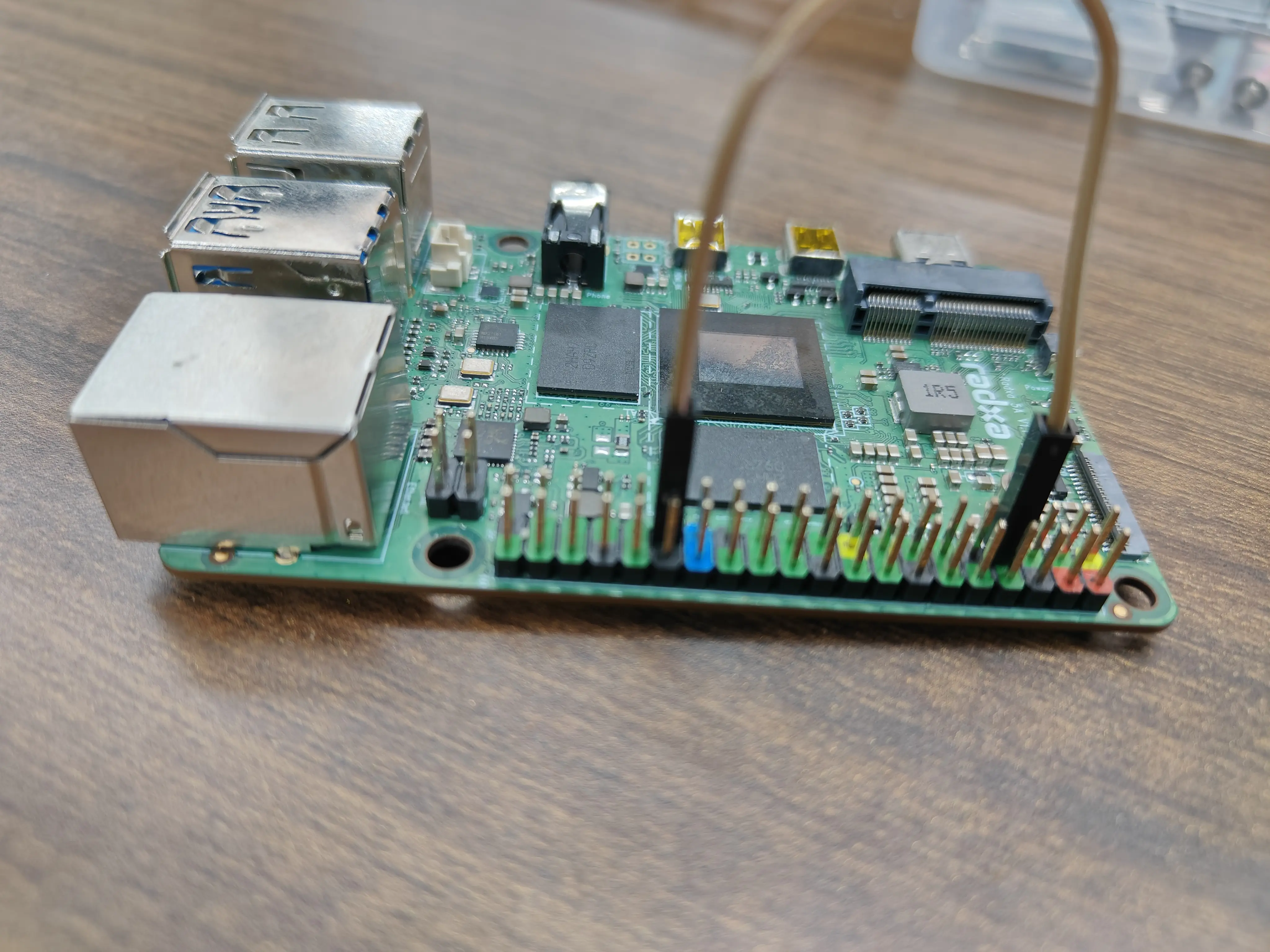
As shown in the figure, short the Radxa ROCK 5A UART4-M2's PIN_7 and PIN_29
Test
- Open a terminal and enter the following command in the terminal to set the serial port parameters
radxa@rock-5a:~$ sudo stty -F /dev/ttyS4 speed 115200 cs8 -parenb -cstopb -echo
- In the terminal, enter the following command to send data cyclically
radxa@rock-5a:~$ while true ;do echo "sss" > /dev/ttyS4; sleep 1; done;
- Create a new terminal and enter the following command to receive data
radxa@rock-5a:~$ sudo cat /dev/ttyS4
Transceiver test
Enable Overlay
Please refer to Device Tree Configuration to enable UART Related Overlay, eg: "Enable UART4-M2 and UART6-M1".
Connection
Connect UART4-M2 and UART6-M1 as follows
| UART4-M2 | <--> | UART6-M1 |
|---|---|---|
| PIN_7 | <--> | PIN_21 |
| PIN_29 | <--> | PIN_19 |
As shown:
Test
- Open a terminal and enter the following command in the terminal to set the serial port parameters
  radxa@rock-5a:~$ sudo stty -F /dev/ttyS4 speed 115200 cs8 -parenb -cstopb  -echo
  radxa@rock-5a:~$ sudo stty -F /dev/ttyS6 speed 115200 cs8 -parenb -cstopb  -echo
- In the terminal, enter the following command to send data cyclically
UART4-M2 i.e ttyS4 as the sender
radxa@rock-5a:~$ sudo stty -F /dev/ttyS4 speed 115200 cs8 -parenb -cstopb -echo
- Create a new terminal and enter the following command to receive data
UART6-M1 i.e ttyS6 as the receiver
radxa@rock-5a:~$ sudo cat /dev/ttyS6
- validate
The test is successful if the sender successfully sends and the receiver successfully receives the character "ssss".
- Swap sender and receiver for cross validation